
TM 9-2330-356-14
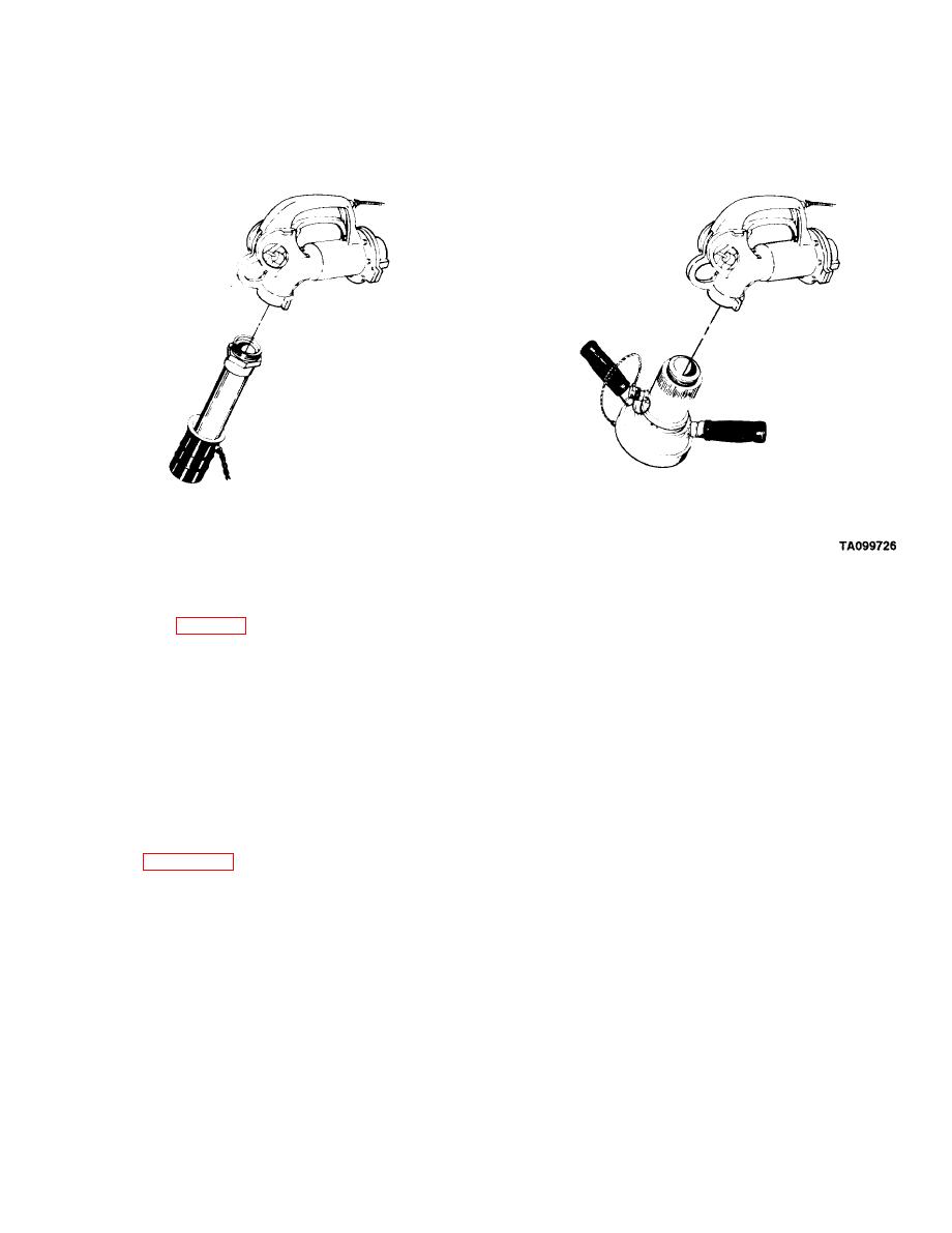
1. Remove spout from overwing nozzle.
2. Install quick disconnect converter.
Refuel on the Move (ROM) Assembly and
NOTE
Operating Procedures (M969 and M969A1)
The number of fueling points to be connected
and operated may vary. Additional hose
sections of the type provided in the kit maybe
connected to the basic ROM system for
WARNING
additional reach if needed to satisfy special
deployment conditions.
Fuel handlers must wear appropriate safety
equipment during fueling operations to avoid
d.
Lay out ROM parts on ground per Instruction
injury.
Drawing 12356089.
NOTE
NOTE
Apply teflon tape to all male coupling threads.
Components of the Refuel Assembly Kit
Reapply as needed during subsequent de-
(NSN 4730-01-295-1842) are listed In
ployments to ensure proper seal of connec-
tions.
e. Attach parts, starting with large 4-inch tee, to the
a.
Select refuel site and park fuel tank semitrailer at
4-inch hose from the fuel tank semitrailer. If equipped,
right side of road.
open valve on tee assemblies before operating.
b.
Open Refuel on the Move (ROM) accessory
Remove dust caps and assemble parts. Ensure
f.
container. Unpack instruction sheets and inventory sheet.
that camlock clamps hold parts together tightly.
Take inventoy of components of container.
g. Place fire extinguishers at refuel sites (8). Place a
c.
Unload the three 4-inch hoses from hose troughs.
ground rod at each refuel site and pound 18 inches into
Remove dust cap from valve B and the three hoses.
ground with slide hammer on ground rod.
Connect the three hoses together and attach one end to
valve B.
h.
Place nozzles on ground rod handle.

