
TM 9-2330-381-14
2-3.
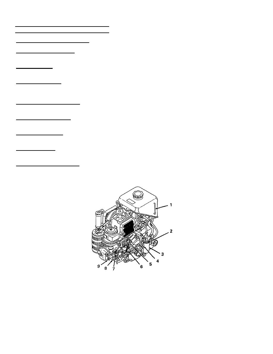
APU CONTROLS AND INDICATORS
FUEL TANK SIGHT INDICATOR (1). A sight tube which shows how much fuel is in the fuel tank.
FUEL PETCOCK VALVE (2). A two-position valve used to allow fuel to flow to the engine in the open position and shut
off fuel when in the closed position. When closed, air is vented from fuel lines and filter.
FUEL FILTER (3). Used to filter fuel coming from the tank. The clear sediment bowl enables you to check the filter for
trapped particles and contaminants.
OIL LEVEL GAGE (4). A dipstick used to measure the oil level in the APU crankcase. Two marks indicate when the oil
level is full or when oil needs to be added. When checking oil level, the gooseneck must be positioned at normal travel
height to achieve an accurate reading.
SPEED CONTROL LEVER (5). APU control box THROTTLE CONTROL cable connects to this lever and is used to
throttle the speed of the APU. Also used to shut down the APU by pushing the lever to farthest right position.
JET START PLUNGER (6). A piston type pump. Pull out and push in to inject fuel into the air intake of the APU as a cold
weather starting aid.
JET START COCK (7). A needle valve which controls the flow of fuel for the jet start plunger. When turned clockwise
(closed), fuel is shut off to the jet start system. When turned counterclockwise (open), fuel flows from the jet start system.
DRAIN VALVE (8). Used to drain the coolant from radiator and engine block. Turn counterclockwise to drain and
clockwise to close. Keep closed during APU operation.
DECOMPRESSION VALVE (9). Used with APU jump start for arctic weather starting of the APU. When held open (up), it
partially opens the exhaust valve of the APU and compression is reduced during cranking. Normal position for this valve
is spring loaded closed (handle pointing down).
2-3

