
TM 9-2330-381-14
4-84. GOOSENECK ISOLATION VALVE ASSEMBLY (CONT)
CAUTION
The ball valves must be arranged so that all ball valves operate in the same
direction or damage to equipment or premature system failure may result.
3.
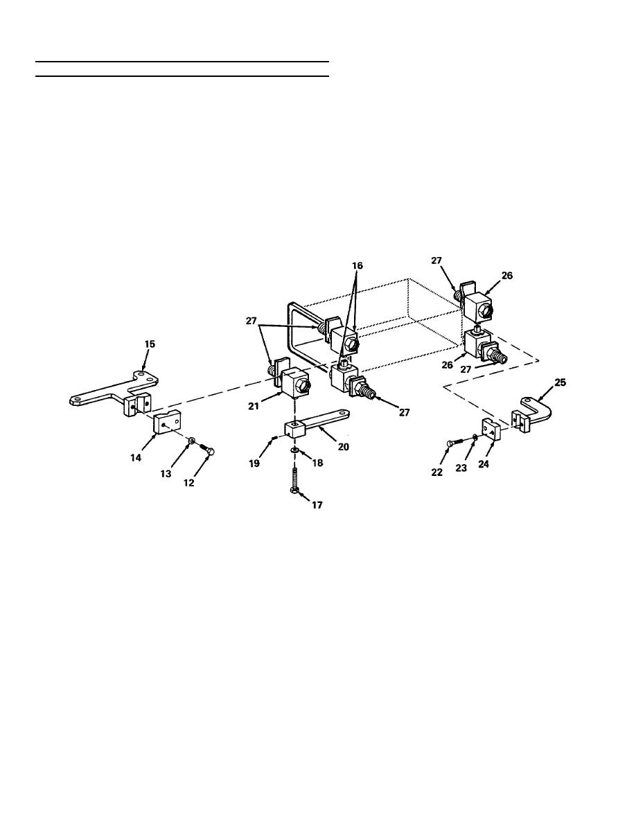
Check that all five ball valves (16, 21, and 26) are set with each ball in open position.
4.
Aline and install five ball valves (26, 21, and 16) onto platform weldment, passing five bulkhead fittings (27) to
platform mounting plates. Hand tighten jam nut on each of five bulkhead fittings (27) so that ball valves can move
slightly.
5.
Aline manual control lever (25) and clamp bridge (24) between two ball valves (26) and secure in place by
installing two washers (23) and self-locking bolts (22).
NOTE
Check position of each ball valve by looking through one of the ports on the valve
as the valves are operated.
6.
Operate manual control lever (25) and check that ball in each ball valve (26) is moving the same amount and in
the same direction.
a. If each ball in ball valves (26) works properly, tighten down nut on each bulkhead fitting (27) for both ball valves
(26).
4-414

