
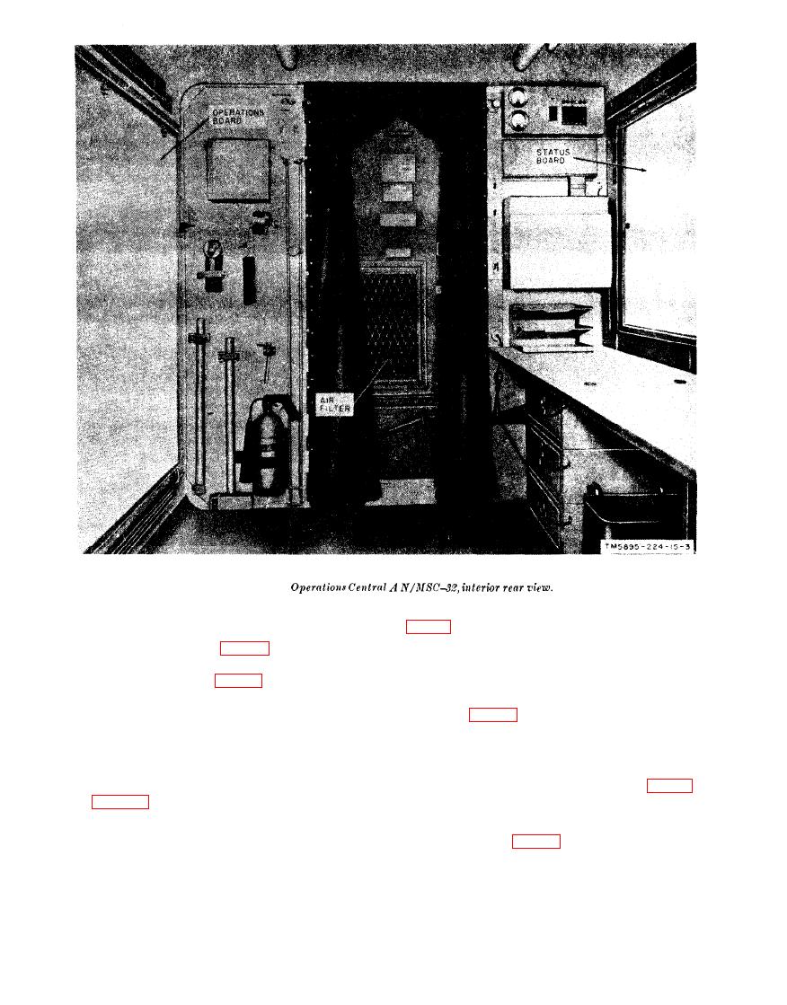
Figure 6.
(not shown) which muffle the sound when the
exhaust blowers are operating. Exhaust vents
are secured in their mounting bases on the
to the outside of the shelter are provided.
floor of the shelter (fig. 12 and 13). Each
heater contains a 1.5-kilowatt heating element
d. Distribution Box J-1077A/U. The J-
and a fan for air circulation. H o r i z o n t a l
1077A/U (fig. 13) is a terminal box which
louvers on the front of each heater are adjust-
can be used to connect field wires to a 26-pair
able to deflect the airstream. Operating con-
cable connector.
trols are on the top of each heater.
e. Clock. An 8-day luminous-dial 24-hour
b. Intercommunication Station LS-147(*)/
clock is mounted on the f ront wall (fig. 13).
The
LS-147(*)/FI
provides
A knob on the left-hand side is used for wind-
two-way nonprivate communication in a sys-
ing and setting the clock.
tem that consists of other LS-147(*)/FI's or
equivalent equipment.
panel provides a means of rearranging the
SB-22(*)/PT and the TH-5/TG circuits.
c. Exhaust Blowers. Two exhaust blowers

