
TM 55-1925-282-14&P
0018 00
BACKFLOW PREVENTER VALVE REPAIR
DISASSEMBLY
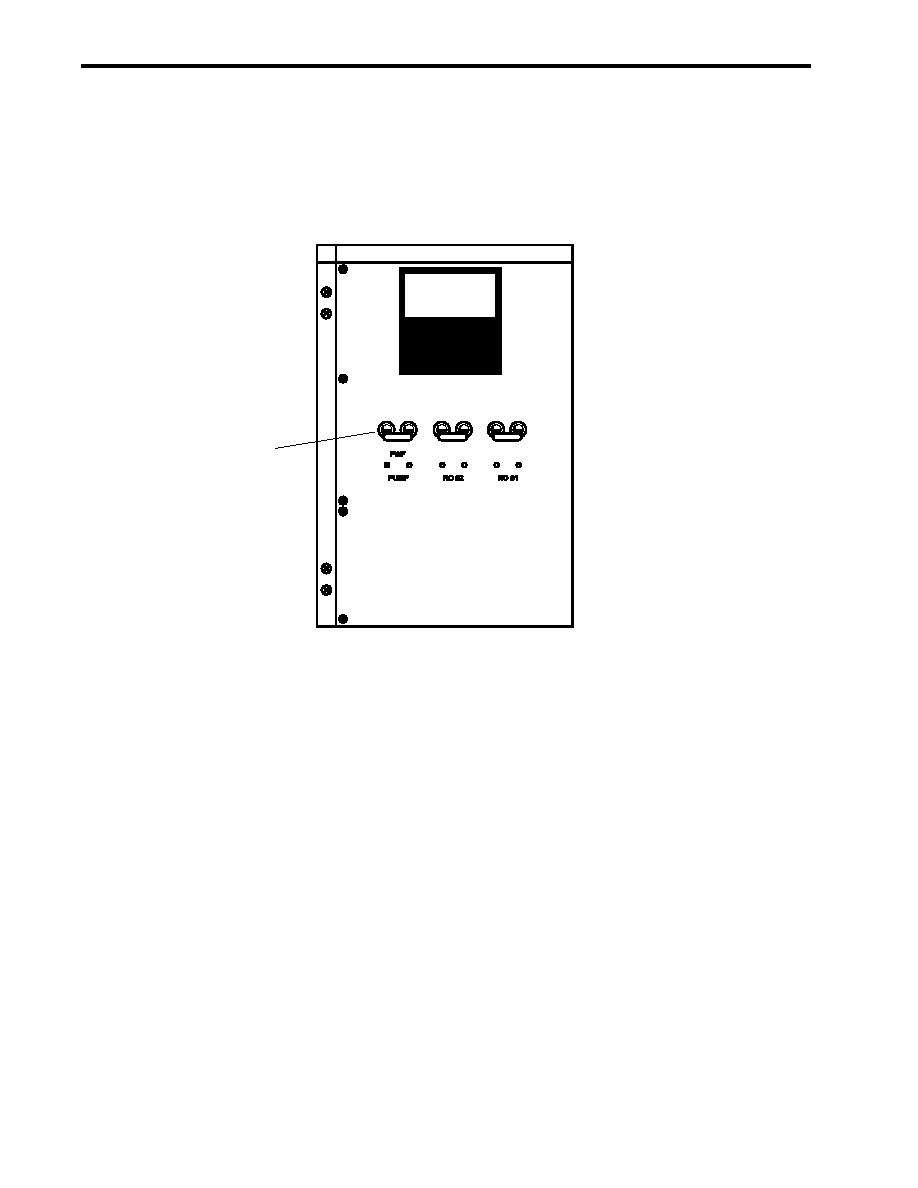
1. Set to OFF the FWF PUMP circuit breaker (figure 7, item 1) at the 24 Vdc control panel. Lock out and tag out
(FM 55-502).
1
Figure 7. 24 Vdc Control Panel
2. Close the backflow preventer supply valve RO-V-6 (figure 8, item 1). Lock out and tag out (FM 55-502).
3. Close the backflow preventer discharge valve RO-V-7 (figure 8, item 2). Lock out and tag out (FM 55-502).
4. Remove the four cover bolts (figure 8, item 3) and remove the valve cover (figure 8, item 4) from the valve
body (figure 8, item 5).
NOTE
The cover O-ring, diaphragm, and stem may remain attached to the valve cover, and
can usually be removed as an assembly.
5. Remove the cover O-ring (figure 8, item 6), diaphragm (figure 8, item 7), and stem (figure 8, item 8). Discard
the cover O-ring and diaphragm.
6. Remove the valve spring (figure 8, item 9).
7. Remove the retainer (figure 8, item 10) from the valve body (figure 8, item 5).
0018 00-8

