
TM 55-1925-284-14&P
0029 00
7. Remove the gasket (figure 1, item 10) from the gearbox cover (figure 1, item 8). Discard the gasket.
8. Through the blower pipe connection (figure 1, item 11), place an alignment mark on the strip
(figure 1, item 12) of one impeller (figure 1, item 13) and on the mating waist (figure 1, item 14) of
the other impeller using a piece of chalk or an indelible marker.
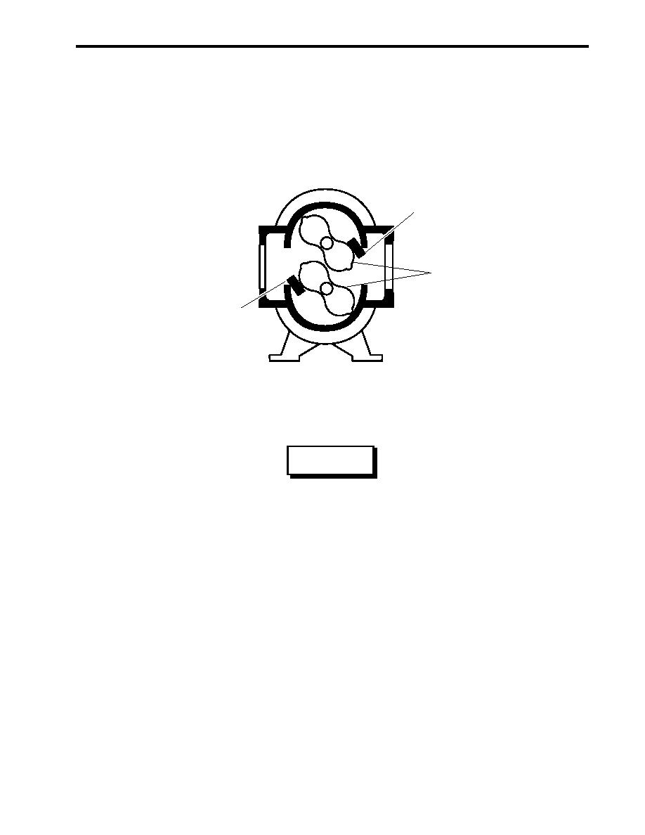
9. Wedge the impellers (figure 2, item 1) with blocks of hardwood (figure 2, item 2) to keep them from turning
during disassembly.
2
1
2
Figure 2. Impeller Removal
WARNING
Do not remove the gear nuts completely before the gears are unseated from the
taper fits of the drive shafts. Failure to comply with this warning may result in
severe injury or death.
10. Loosen, but do not remove, the gear nuts (figure 1, item 15) from the drive shafts (figure 1, item 4).
NOTE
As the mechanical puller setscrew is turned, the mechanical puller will have a tendency
to spin, hitting the teeth of the other gear. To prevent this, hold the puller corner nut with
a wrench while rotating the setscrew.
11. Using a mechanical puller, unseat the gears (figure 1, item 16) from the drive shafts (figure 1, item 4).
NOTE
Mark each gear to its drive shaft and make a note of each gear's location prior to re-
moval from the drive shafts, so they can be returned to the same shaft during assembly.
12. Remove the gear nuts (figure 1, item 15) and the gears (figure 1, items 16) from the drive shafts (figure 1,
item 4). Note the location of each gear for use during assembly.
0029 00-3

