
TM 55-1925-285-13&P
0003 00
SAMPLING/SENSOR ASSEMBLY
The sampling/sensor assembly is comprised of two parts: the nozzle sampler and the sampling/sensor assem-
bly (the control box). The sampling/sensor assembly is further subdivided into two compartments. One compart-
ment houses the Sample and Detection Subassembly (SDA) and the other compartment houses the electronic
components and controls of the OCM. All of the effluent oil content measurements are made by this assembly.
The theory of operation for each of these three sections is detailed in the paragraphs below.
NOZZLE SAMPLER
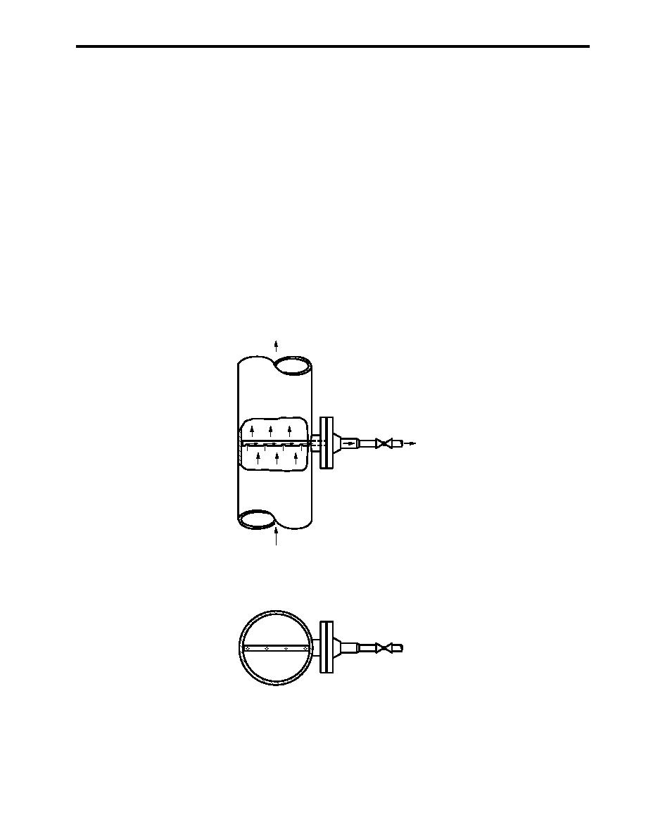
The effluent sample is taken from the OWS effluent discharge through a nozzle sampler (figure 3, item 4;
figure 4). This device takes a sample from the effluent stream, which is uniform and typical of the effluent being
discharged from the OWS. The OWS effluent pressure delivers the sample to the sampling/sensor assembly.
The effluent is pressure regulated at 5 to 25 PSI (0.3 to 1.7 bar) at the sample inlet of the sampling/sensor
assembly. Nominal 3/8-inch piping (or tubing) connects the nozzle sampler to the sample inlet on the sampling/
sensor assembly.
FLOW
NOZZLE
TO OCM SAMPLE
SAMPLER
INLET
OWS EFFLUENT
DISCHARGE
CROSS-SECTION OF OWS
EFFLUENT DISCHARGE PIPING
WITH NOZZLE SAMPLER
Figure 4. Nozzle Sampler, General Arrangement
0003 00-5

