
TM 55-1925-285-13&P
0009 00
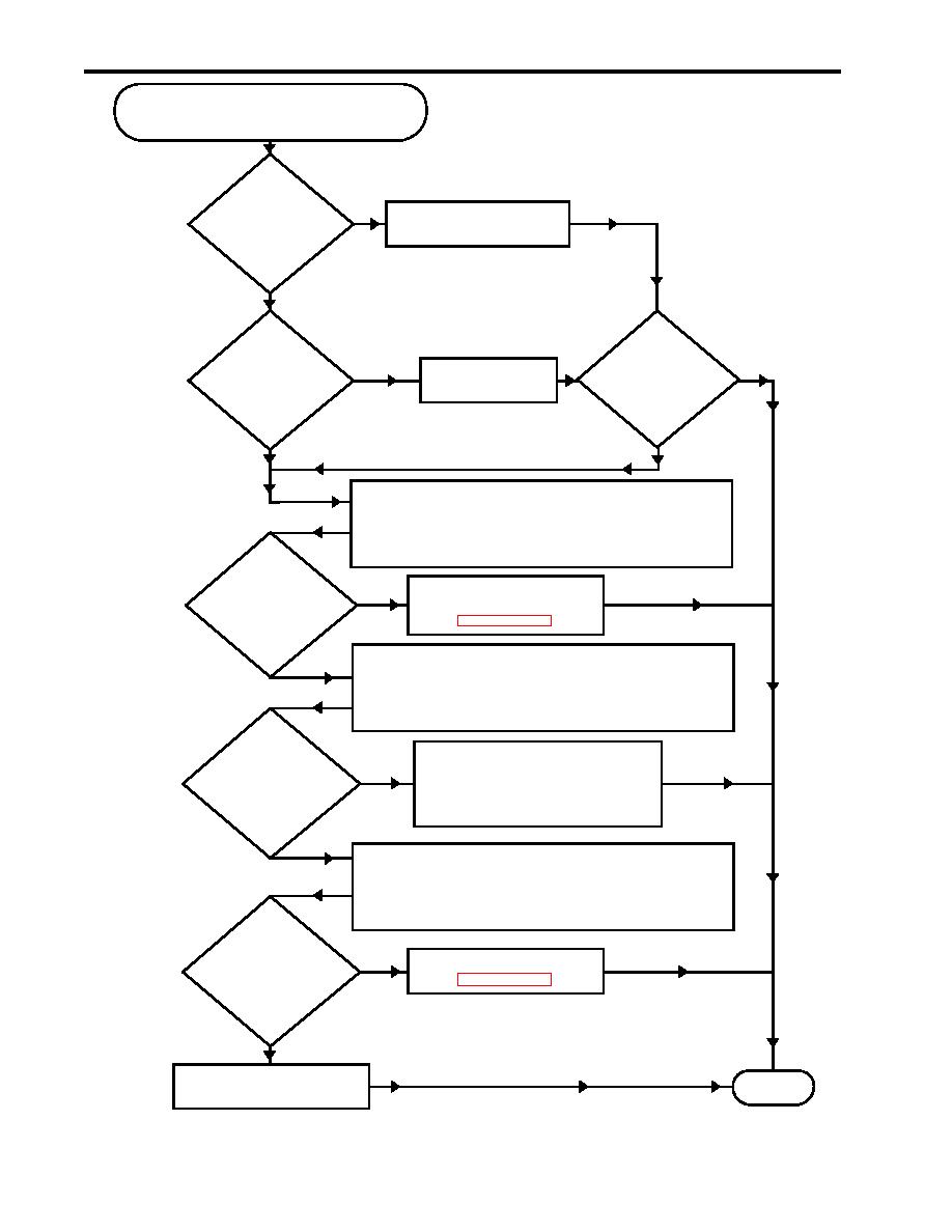
Remote Indicator (Alarm) Assembly
Indicators Inoperative While OCM
is Operating
Is the
OCM switch
No
Place OCM switch A1S2
A1S2 in the
in the REMOTE position.
REMOTE
position?
Yes
Is
Are the
the J2 cable
remote indicator
Yes
No
Securely connect
securely connected
(alarm) assembly
the J2 cable.
to the bottom
indicators
of the
operating?
unit?
No
Yes
Warning:
Take great care when working around energized
electrical equipment. Contact between
unprotected body parts and electrical conductors
can cause serious injury.
Is 120 Vac
present across
Replace the remote
Yes
terminals 2 and 3
indicator (alarm) assembly
on the alarm PCB
(WP 0015 00).
(figure 3,
item 1)?
Warning:
No
Take great care when working around energized
electrical equipment. Contact between
unprotected body parts and electrical conductors
can cause serious injury.
Is 120 Vac
Defective cabling between the
present across
sampling/sensor assembly and
Yes
terminals 2 and 4
the remote indicator (alarm)
on the power PCB
assembly. Notify the maintenance
(figure 1,
supervisor.
item 3)?
No
Warning:
Take great care when working around energized
electrical equipment. Contact between
unprotected body parts and electrical conductors
can cause serious injury.
Is 120 Vac
present across
Yes
Replace the power PCB
terminals 1 and 2
(WP 0016 00).
on the power PCB
(figure 1,
item 3)?
No
Report the defect to the
Exit
maintenance supervisor.
Procedure 18. Remote Indicator (Alarm) Assembly Indicators Inoperative While OCM Is Operating
0009 00-26

