
TM 55-1925-286-13&P
0004 00
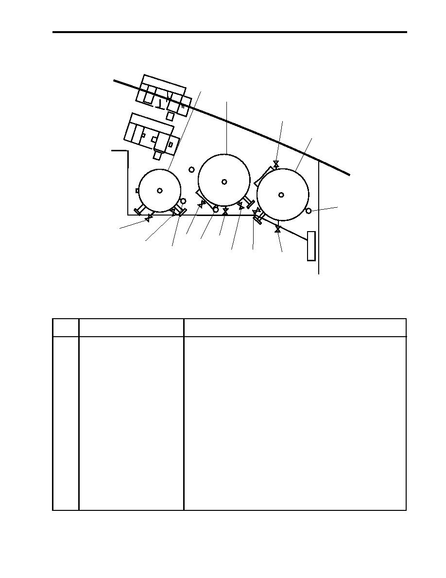
AIR RECEIVERS AND VALVES CONTROLS AND INDICATORS
1
2
3
4
5
20
15
12, 13
14
17, 18, 19
16
10, 11
8, 9
6, 7
Figure 4. Air Receivers and Valves
Table 4. Air Receivers and Valves (refer to figure 4)
Key
Control/Indicator
Function
1
SHIPS SERVICE AIR RCVR
This receiver stores compressed air for the ship's service
compressed air system (Working pressure 125 PSI (8.6bar)).
2
STARTING AIR RCVR NO. 2
This receiver stores compressed air for the starting air system
(Working pressure 250 PSI (17.2 bar)).
3
CA-97 Cutoff Valve,
This valve secures the pressure to the air compressor regulator.
Air Compressor Regulator
4
STARTING AIR RCVR NO. 1
This receiver stores compressed air for the starting air system
(Working pressure 250 PSI (17.2 bar)).
5
Pressure Gauge, STARTING
This gauge indicates the air pressure present in the starting air
AIR RCVR NO. 1
receiver 1 (Working pressure 250 PSI (17.2 bar)).
6
CA-47 STG AIR TK DR
This valve is located below the deckplate. When OPEN, this valve
valve drains condensation and air from starting air receiver 1.
7
CA-50 AUTO DR
This cutoff valve prevents the automatic drain valve from operating.
0004 00-5

