
TM 55-1930-203-10
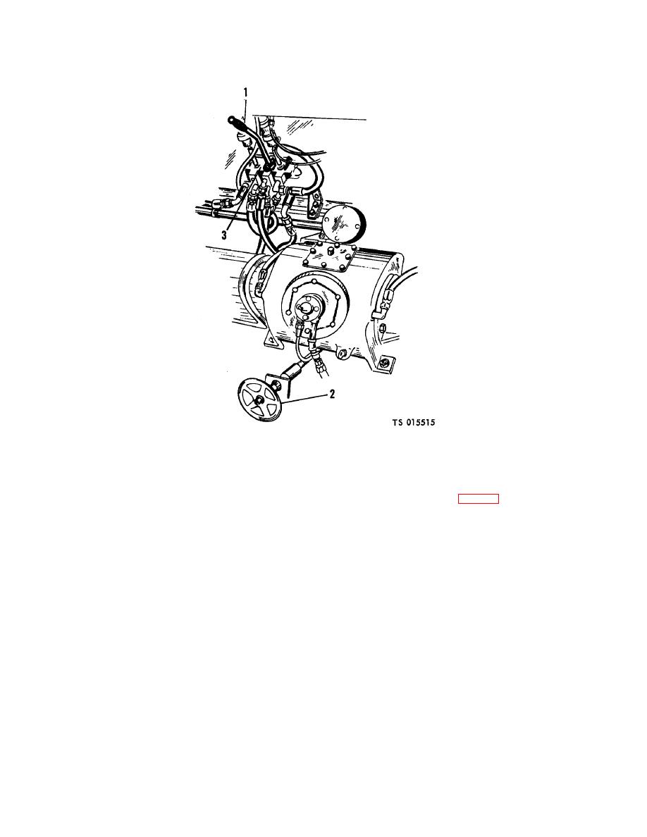
1 Port bilge pump control lever
2 Bilge drain handle
3 Multiple unit valve
Figure 2-7. Controls in center hatch, port side.
2-24. Ramp Controls
a. General. The ramp hydraulic system, controlled by two manually operated pilot air valves (5, fig. 2-8) located on the port and
starboard forward main deck, is used to raise and lower the ramp. The pilot air valves have three positions: RAISE, NEUTRAL, and
LOWER. Moving the control lever from neutral to lower or raise position will apply air pressure to a double acting air cylinder, which
actuates the corresponding section of a multiple unit valve. When the control lever is in RAISE position, the multiple unit valve
allows hydraulic fluid to flow to the ramp cylinders. LOWER position allows fluid in the ramp cylinder to flow back to the hydraulic oil
tank. The fluid returning to the hydraulic oil tank from the ramp cylinders, when the ramp is being lowered, is blocked by a check
valve and flows through a fluid flow restrictor which is in parallel. The fluid flow restrictor controls the rate of ramp descent by
restricting fluid flow back to the hydraulic oil tank. The operator may use the control lever on either side to raise the ramp, if at least
one port and one starboard engine is operating. With one or both engines operating on one side only, the ramp may be raised with
the control lever on the engine operating side. The ramp can be lowered with either control lever.
NOTE
Since the bilge pumps and the ramp cylinders use the same hydraulic circuit, the bilge pumps and ramp cannot
be operated simultaneously.
A quick-opening self-closing valve, located on the inboard side of the starboard bulkhead, is activated by a trip lever each time the
ramp is
2-17

