
TM 55-4920-399-13&P
Table 2-1. Cable Hookups
--
(2) Adaptor Cable Assembly
(1) Adaptor Cable Assembly
(Master Cable To AC Wiring)
(Master Cable To Indicator)
Aircraft
1000961-2
1000961-1
CH47A, B
USE 1000963 MASTER CABLE ONLY
CH54B (Main Tanks)
1000961-3
1000961-4
CH54B (Aux Tanks)
1000961-5
1000961-6
AH-1
UH-1
1000961-7
1000961-8
OV-1
Switchbox 1001032 is connected to AC fuel system wiring aft and above the
CH-47C
cockpit (main fuselage) door. When measuring fuel tanks, connect switchbox to
aft portion of junction ONLY and use cables 387386-1200 and 384006-1200 for
connection to test set.
e. Adjust COMPENSATOR SIMULATOR for
the desired value, using its SET knob.
accomplished, perform steps per paragraph 2-2a
through m.
NOTE
a. Turn the MODE SELECT switch to the
MEAS INT position.
If the compensator simulator will not be
used, place the Shorting Plug, 387398,
b. Place the T/U - COMP switch in the T/U
on LO-Z COMP.
position.
c. Adjust TANK UNIT SIMULATOR for the
f. Put the MODE SELECT switch in the SIM
desired value, using the SET knob.
position to allow capacitance to be simulated to the
aircraft indicator.
NOTE
The SET knob is normally a 40:1 ratio
NOTE
but can be pressed and turned for a 1:1
If the capacitance meter flashes 8888,
ratio.
this indicates the capacitance is beyond
the selected range.
d. Place T/U - COMP switch in the COMP posi-
tion.
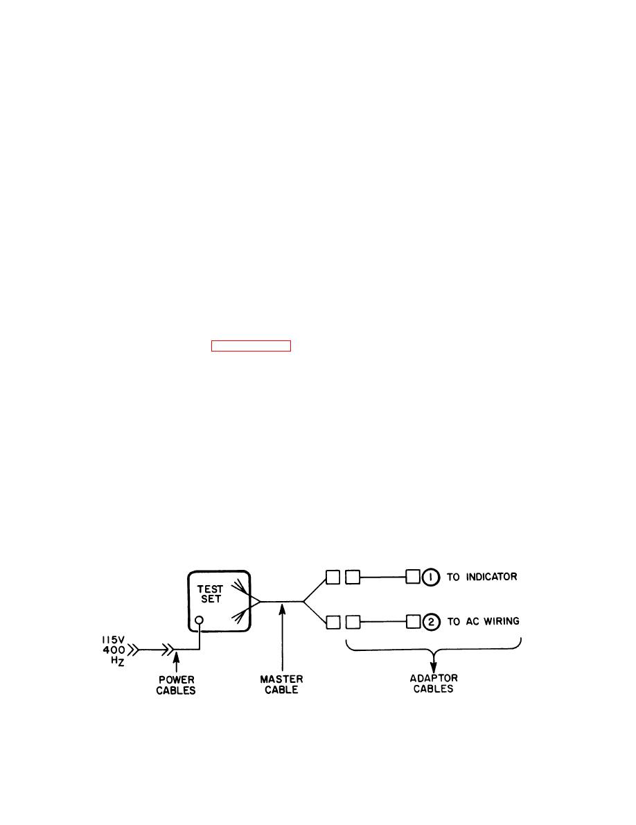
Figure 2-1. Typical cable connection block diagram
2-2

