
TM 9-1550-416-14&P
(2)
Attach neck straps to neck strap eyelets.
4-12
TRANSMITTER TRAINER CORD ASSEMBLY
PROCEDURES.
(3)
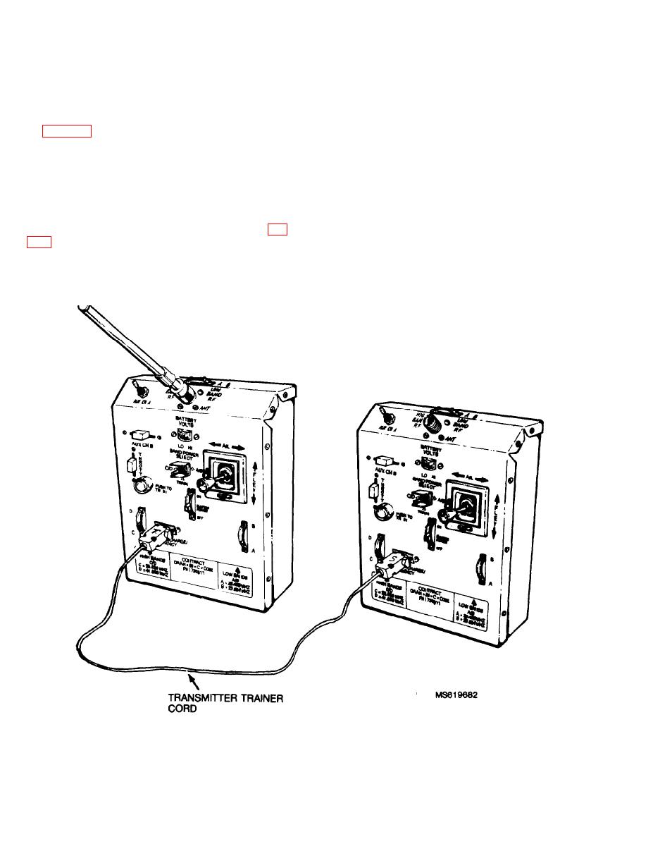
Connect the transmitter trainer cord.
(a) Connect the end of the transmitter trainer
a. Obtain the following items. (For item identification,
cord marked T (instructor) to the TRAINER/CHARGE/
see figure 4-6.)
EMERGENCY connector on the instructor transmitter.
Two transmitters
(b) Connect the other end of the cord marked
Two neck straps
S (trainee) to the TRAINER/CHARGE/ EMERGENCY
One transmitter antenna
connector on the trainee transmitter.
Transmitter trainer cord from GSE field box
(4) Set the Band Power Select switches on the
b. Inspect the components for damage. Repair or reject
transmitters:
as appropriate.
(a) Set the Band Power Select on the
c. Perform the assembly procedures as follows (See fig.
instructor's transmitter as required to match the receiver
channel.
(1) Connect the antenna to one of the transmitters.
(b) Set the Band Power Select switch on the
Tighten antenna sleeve "finger tight" (approximately 10-12
trainee's transmitter to TRAIN.
in/lbs). This will be the instructor unit.
(5) Both transmitters must be turned ON to operate
in the instructor/trainee mode.
Figure 4-6. Instructor/trainee cable hookup.
4-8

