
TM 9-2320-211-10
(7) Energize auxiliary power supply, if used as outside power source.
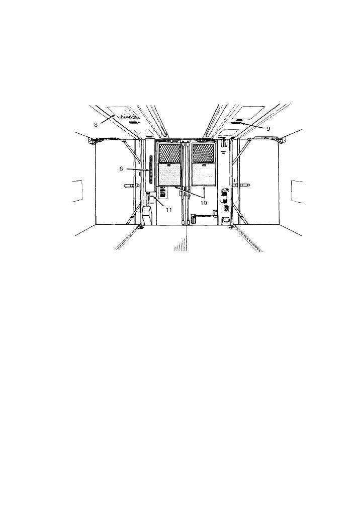
e. Ceiling Lights and Service Receptacle.
NOTE
Refer to instruction plate on circuit breaker switch panel for identification of each
circuit breaker.
(1) Normal light operation:
(a) Place the 208-volt main circuit breaker, on switch panel (6), in ON position
(b) Place the main blackout circuit switch (11) in OFF position.
(c) Place all service receptacle and blackout switches (9) in OFF position.
(d) At main switch panel (6), place the ceiling lights and service receptacle 120-volt
circuit breaker switches in ON position.
(e) Operate individual ceiling light switch (8) as needed.
(f) When operation is completed. place ceiling light, service receptacle, and 208-volt main
circuit breakers in OFF position.
(2) Blackout light operation.
(a) Raise all side and rear window blackout panels (10)
(b) At main switch panel, place 208-volt main circuit breaker in ON position.
(c) Place main blackout circuit switch (11) in ON position.
(d) At main switch panel, place ceiling light, blackout circuit and service receptacle
circuit breakers in ON position,
TA 067071

