
Insert the cotter pin into the hole in the end of the
at the second wheel. Fasten the other ends of the
rod behind the lever and bend it back.
conduits to the frame cross member with the cable
b. Install Brake Assembly. Refer to paragraph 4-
clamps. Secure the clamps by installing and
10 b.
tightening the clamp bolts, lockwashers, and hex
c. Install Brake Shoe. Insert anchor pins through
nuts. The bolt heads should be on the clamp side of
holes in anchor pin plate, brake shoes, and cams.
the frame member. Place the middle portion of the
Spread brake shoes to clear brake shoe struts on
cable in the equalizer. Insert the cable adjusting
brake backing plate and guide anchor pins through
rod, with the lock nut assembled from the convex
holes in backing plate. Secure anchor pins with
side of the equalizer, so that it holds the cable in the
lockwashers and nuts. Close shoes into strut
equalizer. Install the adjusting nut and second lock
notches and install brake shoe return spring. If
mut to the rod. Adjust cable tension. (para 4-17 c).
removed, install brake adjusting eccentrics and
secure with lockwashers and nuts.
adjusting rod in the hole in the short arm of the
bellcrank. Insert the bellcrank pivot bolt through
Compress the brake cable spring toward the end of
the bellcrank and frame member and install the
the cable so that the cable can be slipped into the
slotted nut and the cotter pin. Hook the hand lever
clamp on the rear of the brake backing plate.
rod through the hole in the long bellcrank arm and
Fasten the cable end into the brake lever with the
secure it with the cotter pin.
clevis pin and insert the cotter pin and bend it
f. Install the Hub and Drum Assembly. Refer to
back. Position the cable conduit in the clamp and
tighten the clamp. Repeat the foregoing procedure
Section IX. TOWING ATTACHMENTS
4-21. Lunette
lunette support bracket after it has been cleaned
a. Removal. Remove the cotter pin from the shaft
keyed washer, and castle nut onto the end of the
end of the lunette and remove the lunette castle nut.
shaft in that order. Tighten the nut so that the
Remove the keyed washer, lunette spring, and
cotter pin hole in the shaft is in line with one slot of
spring washer from the lunette shaft. Pull the
the nut. Insert the cotter pin and bend it back
lunette forward out of the lunette support bracket.
around the nut. Lubricate the lunette (para 3-1).
b. Installation. Slip the lunette shaft into the
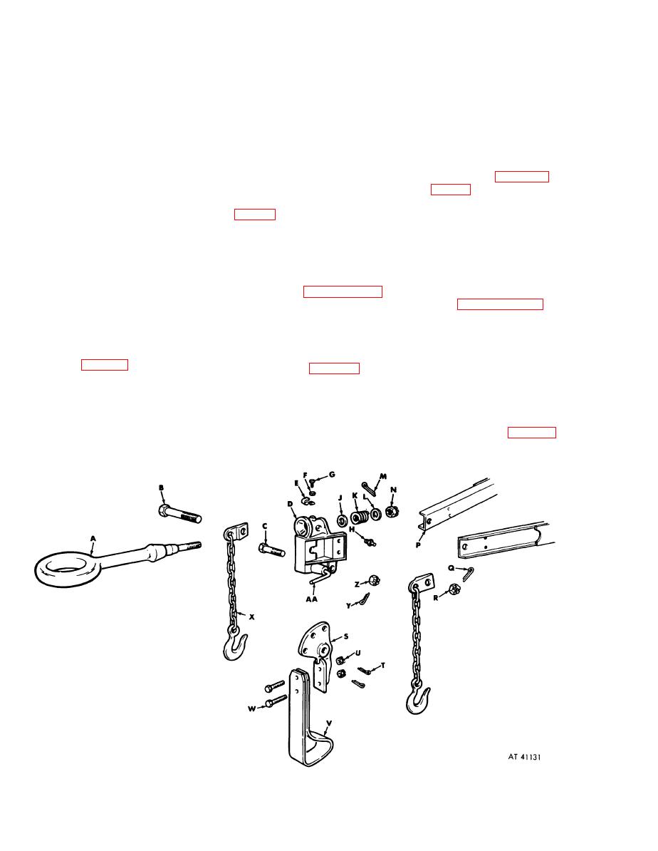
Figure 4-10. Lunette support bracket attachments--exploded view.
4-12

