
5-7. Inspection of Taillight Assembly
a. Check the rubber parts, the grommets,
gasket, a n d c a b l e insulation,
for cracks,
deterioration, and fit, replacing any damaged parts.
b. Inspect the screws for damaged threads and
missing lockwashers and check the internal housing
threads using a thread gage, tap, or good screw.
The threads should be clean and free fitting.
c. Inspect the baffle plate, socket plates, shell
connectors, a n d bushings. Bent, cracked, or
otherwise damaged parts must be replaced.
d. Inspect cables, terminals, and contacts for
corrosion and dirt.
a. Assemble Internal Parts on the Cables. Push
the terminal ends of the cables through the springs,
socket plates, baffle plate grommet, baffle plate,
and body grommet in the order named. Position the
baffle plate grommet in its hole in the baffle plate.
Push the ends of the cables through the hole in the
rear of the body and position the body grommet in
the hold. Seal the cables in the body grommet and
seal the body grommet in the body with gasket
cement.
b. Assemble Baffle and Socket Plates. Slip the
baffle plate into the housing so that the plate covers
the body grommet. Insert the three filister bead
machine screws, through the baffle plate and
grommet, into the body and tighten them. Slip the
eyelets into the socket plates and position the socket
plates in the body. Assemble and tighten the four
machine screws through the socket plate eyelets
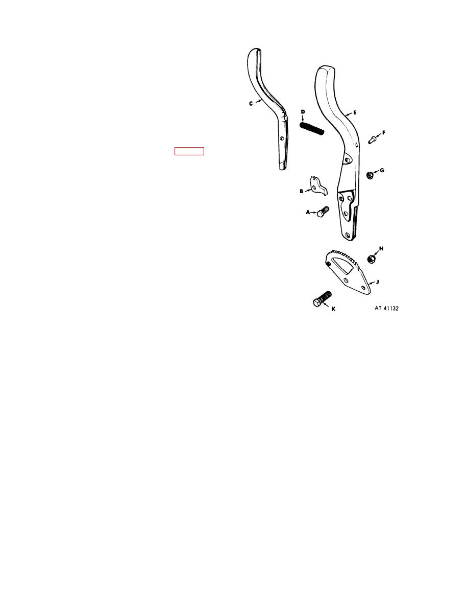
AScrew, cap
into the body.
B P a w l , Locking
c. Assemble the Connector Parts to the Cables.
CLatch
Slip the bell-type connector shells, small openings
D S p r i n g , Latch
first, over the ends of the cables. Slip the terminal
E S h a f t , Hand Lever
connector bushings, small diameters first, over the
F R i v e t , Hand Lever
GNut,
Safety
cable ends. Work the terminal connector grommets
HNut, Safety
over the cable ends, small ends first, and position
J R a c t c h e t , Hand Lever
them properly (fig. 4-8).
KScrew, Cap
d. Assemble Door Assembly. Place the six special
door screws in the door and fasten the retaining
rings in the screw grooves on the hack of the door.
Install the lamps and the door and gasket to the
body.
5-9. Disassembly of the Brake Hand Lever
Straighten the shaft or latch if bent and replace
Assembly (fig. 5-1)
damaged parts. The pawl should be carefully in-
Remove the safety nut and capscrew holding the
spected, particularly for elongation of the pivot hole
pawl and slide the pawl out of the shaft. Drill out
and damage to the point. Test spring for suitable
the lever assembly rivet and remove it. This frees
action. These items shoud be replace if found to
the latch and spring from the shaft.
be damaged.
5-2

