
TM9-2330-207-14
5-6. INTERNAL BRAKES (Cont)
Place washer on camshaft (fig. 4-39). Following marks made at removal, insert camshaft
(e)
into mounting bracket from outer side of backing plate. Slide camshaft into place carefully
using rotary motion to position it in bearings and seals without damage.
Install two washers and one spacer over splined end of camshaft and against camshaft mount-
(f)
ing bracket.
Apply a thin coat of oil on splined end of camshaft and slide slack adjuster (fig. 4-39) into
(g)
position. A slight rotary motion of slack adjuster will allow splines in slack adjuster to mesh
with splines on camshaft.
Position washer on splined end of camshaft and install snap ring.
(h)
(i)
Turn worm shaft of slack adjuster (fig. 4-42) until arm can be positioned in brake air chamber
yoke. Coat 1/2 X 1-13/64 clevis pin with light film of oil and attach arm of slack adjuster to
yoke (fig. 4-39). Secure clevis pin with 1/8 X 7/8 cotter pin.
Install brake shoes (para. 4-40b).
(j)
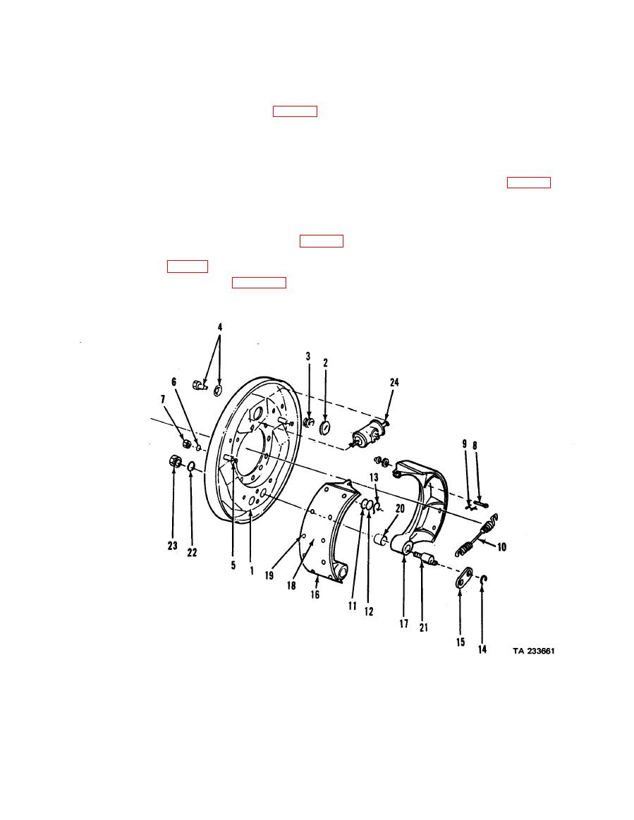
5-7. INTERNAL BRAKES (A2C MODELS)
7. Nut
13. Ring
1. Plate Assy
19. Rivet
8. Pin, spring
14. Washer
2. Cam
20. Bushing
9. Pin, round
15. Strap
3. Spring
21. Pin
10. Spring
4. Pin & Washer
16. Brake Shoe Assy
22. Washer, lock
11. Washer
17. Shoe, brake
5. Pin
23. Nut
12. Washer
18. Lining, brake
6. Washer, lock
24. Wheel cylinder
5-7

