
TM9-2330-207-14
a. lnspection. Examine body cable plugs for loose connections or bent and damaged pins. Visually inspect
insides of 110-volt switch box and circuit breaker load center for any signs of arcing and loose connections.
Check 110-volt wall receptacles for security and signs of over-heating or shorting. Inspect the external 110-
volt power receptacle for security and serviceabiIity.
b. Repair.
Remove all power from vehicle prior to making any repairs on electrical
system.
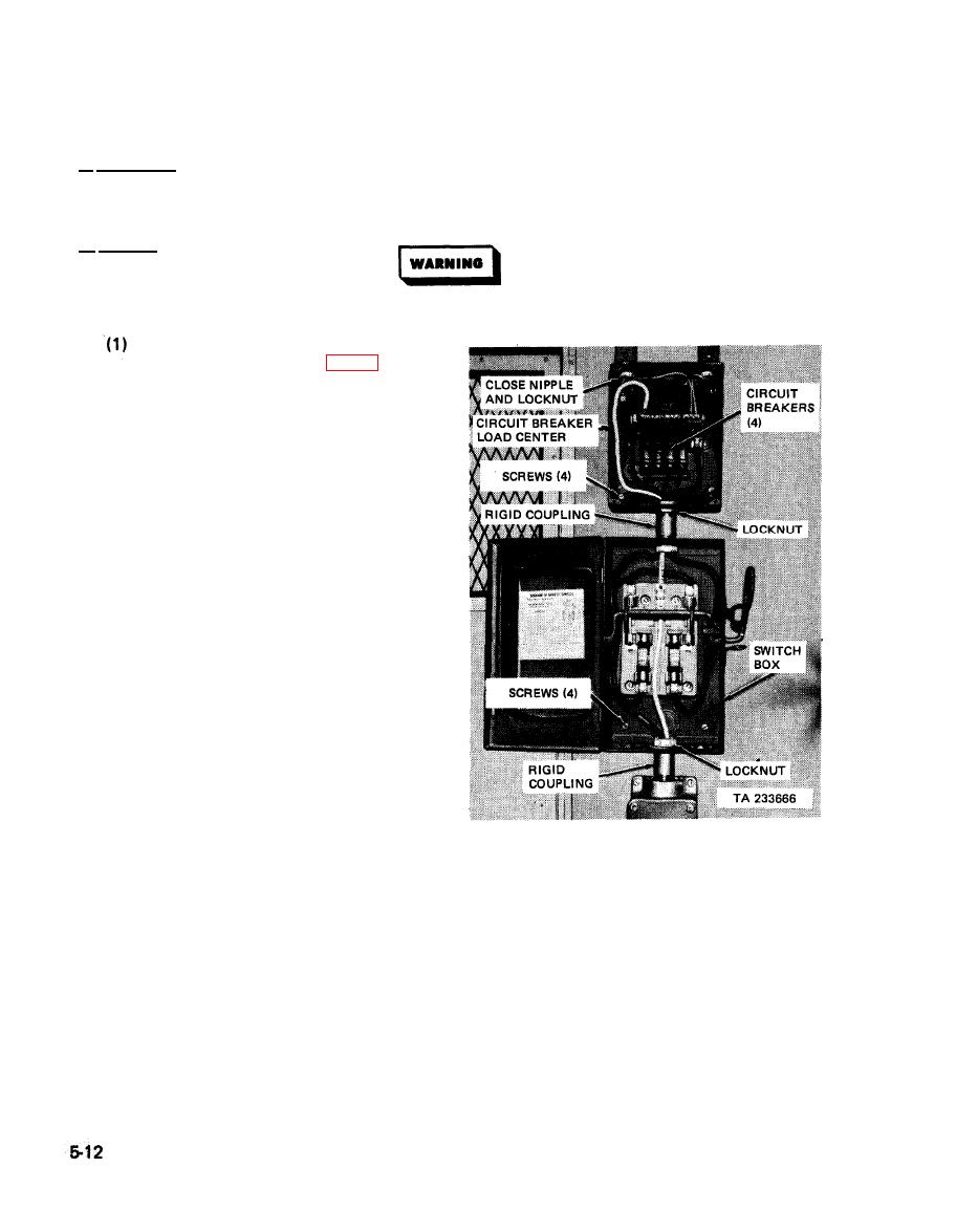
110-volt switch box and circuit breaker
load center (M129 Series, fig. 5-9).
Replace any defective circuit breakers.
To replace a circuit breaker, pull circuit
breaker out and snap a new one into
place. If knife switch in switch box
makes loose contact, press contacts
closer together. If either circuit breaker
load center or switch box are damaged
beyond serviceability, remove and
replace as follows:
(a) Removal.
1. Disconnect all internal wiring
and tag to facilitate instalIation.
2. Unscrew lock nut securing rigid
coupling to switch box and
slide off of wiring.
3. Unscrew one close nipple inside
switch box and three inside cir-
cuit breaker load center and
slide off of wiring.
4. Loosen two locknuts on rigid
coupling between switch box
and circuit breaker load center.
5. Remove two locknuts from inside
and slide off of wiring.
load center, M129 Series - internal view
6. Remove four flat-head screws securing switch box. Remove switch box.
7. Remove four flat-head screws securing circuit breaker load center. Remove circuit breaker
load center.
(b) Installation.
1. Position circuit breaker load center on wall and insert wiring through holes in top; then
secure in place with four No. 12-11 X 3/4 flat-head screws.
2. Insert interconnecting wiring through hole in bottom of load center; slide close nipple
over the wiring; then connect the interconnecting wiring inside the circuit breaker load
center.

