
TM 9-2330-211-14&P
Section V. ELECTRICAL SYSTEM MAINTENANCE
Page
Page
Clearance Light Assemblies ... ...
Wire Connectors.. .
. .....
Composite Light Assemblies . . . . . . . . . .
Wiring Diagram . . . . . . . . . . . . . . . . . . . . .
Ground Wire Repair . . . . . . . . . . . . . . . . .
Wiring Harness . . . . . . . . . . . . . . . . . . . . .
Receptacle . . . . . . . . . . . . . . . . . . . . . . . .
Wiring Harness Repair . . . . . . . . . . . . . . .
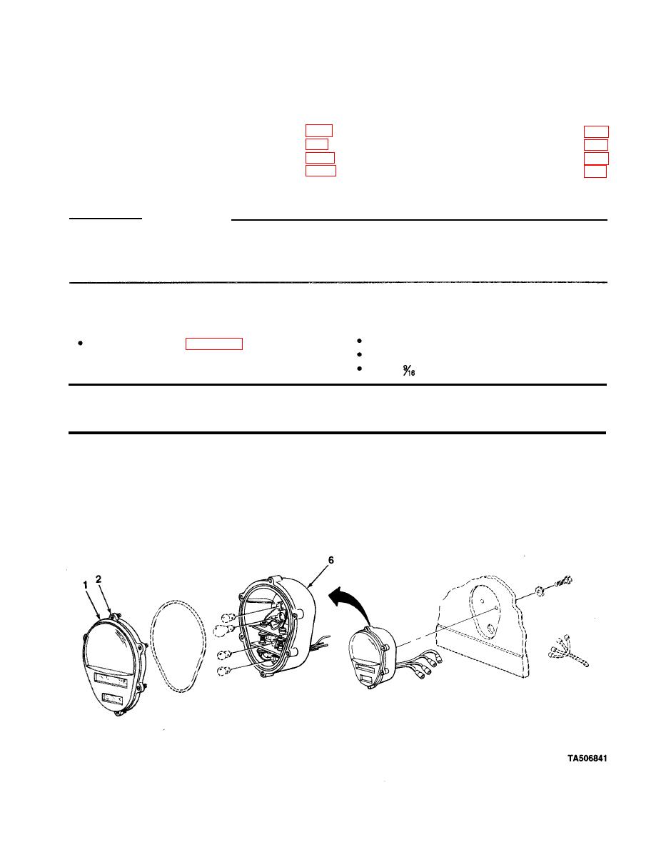
4-12. COMPOSITE LIGHT ASSEMBLIES
This Task Covers:
a. Lamp, Lens, and Door Assembly Replacement
c.
lnstallation of Composite Light Assembly
b. Removal of Composite Light Assembly
Initial Setup:
Materials/Parts:
Tools/Test Equipment:
Handle, ratchet, in. drive
Marker tags (Item 14, Appendix E)
Screwdriver, flat-tip
Socket,
in., in. drive
ACTION
LOCATION
ITEM
REMARKS
LAMP, LENS, AND DOOR ASSEMBLY REPLACEMENT
Door and lens
Six screws (2)
Using screwdriver, unscrew.
1.
assembly (7) to
Screws (2) will stay in door and lens
composite light
assembly (1).
body (6)
4-21

