
TM 9-2330-227-14&P
SERVICE BRAKES, ONE-WHEEL CYLINDER OPTION - CONTINUED
ACTION
ITEM
REMARKS
LOCATION
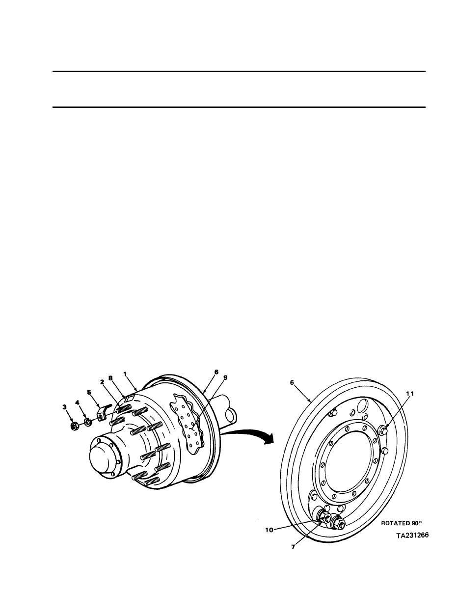
ADJUSTMENT - CONTINUED
Insert 0.005-inch thickness gage
b.
3. Continued
between surface of drum and brake
lining (9).
Using 1/2-inch open-end wrench, turn
Anchor pin (10) and
a.
4. Backing plate (6)
anchor pin until 0.005-inch clearance
locknut (7)
is obtained.
Using 1/2-inch open-end wrench, hold
b.
anchor pin, and using 11/8-inch
open-end wrench, tighten locknut.
Rotate brakedrum until inspection hole
Inspection hole (8)
a.
5. Brakedrum (1)
is 11/2-inch from other end of same
brake lining (9).
Insert 0.010-inch thickness gage
b.
between surface of drum and brake
lining (9).
Cam nut (11)
Using 11/16-inch wrench, turn until
6. Backing plate (6)
0.010-inch clearance is obtained.
Repeat steps 2 thru 6 for other
brakeshoe.
Nut (3), Iockwasher
Put on, and tighten using 5/8-inch socket
Brakedrum (1) and
7.
(4), and inspection
and ratchet handle with 1/2-inch drive.
bolt (2)
hole cover (5)
4-83

