
TM 9-2330-271-14&P
(1) Position ballast (3) and secure with screws.
WARNING
(2) Connect and solder wires.
Disconnect the 110-volt power from
(3) Close cover and secure with mounting
the semitrailer before attempting to
screw.
remove ballast.
f.
Installation (fig. 15).
(1) Remove mounting screw which retains
(1) Connect and solder wires to fixture (1).
ballast cover in place at end of lighting fixture. Hinged
(2) Position fixture on ceiling and secure with
cover will swing down.
eight screws and washers.
(2) Cut wires on load and line sides of ballast
(3) Replace fluorescent lamps (2) (paragraph
(3) as close as possible to splices.
(3) Remove screws securing ballast and
(4) Close cover and secure with screws.
remove ballast.
e. Ballast Installation (fig. 15).
Section VIII. MAINTENANCE OF BRAKE SYSTEM
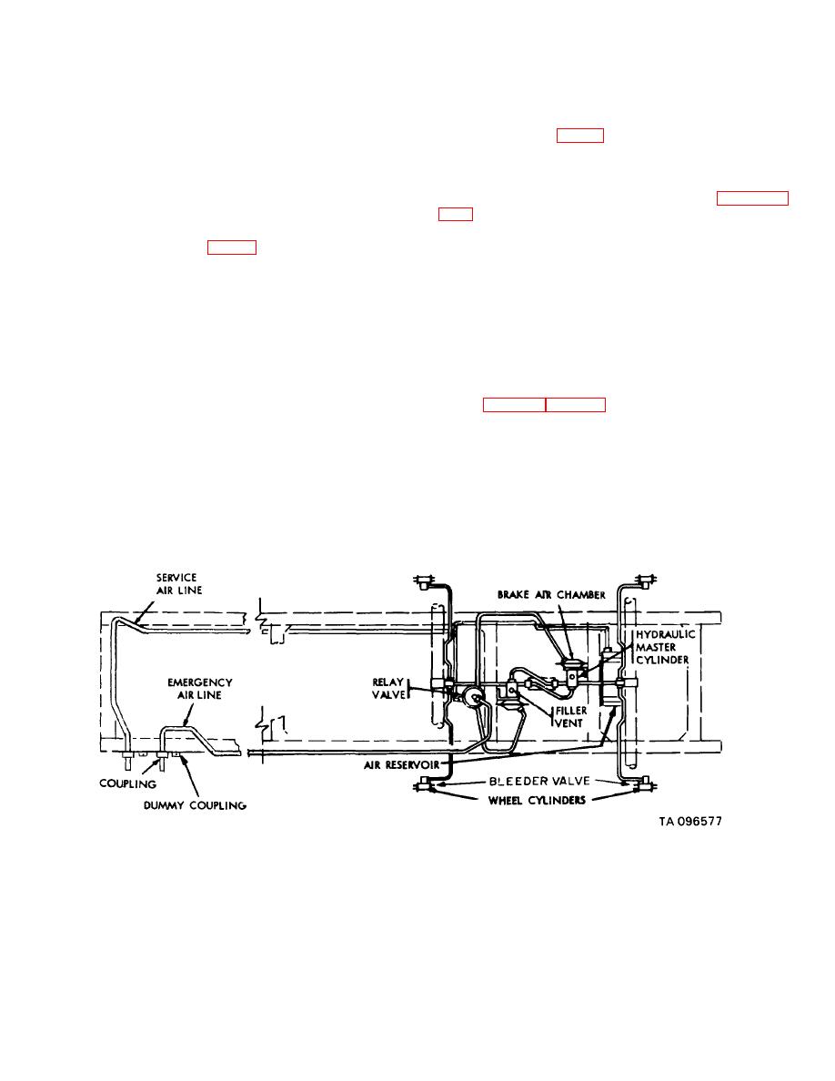
c. Service Brake System. The service braking
4-31.
General
system consists of the relay valve, air-hydraulic master
cylinders, air reservoir, hydraulic wheel cylinders, service
a. Scope. This section covers procedures for
air line, emergency air line, air filters (on some models),
removal and installation of brake shoe assembly, relay
air hose couplings, dummy couplings, and the internal
valves, master cylinder assembly, air chamber assembly,
brake mechanisms that apply the brake linings to the
wheel cylinder assembly, hydraulic and air lines, and air
drums (figs. 4-21 and 4-22.
filter. This section also covers cleaning, inspection, and
repair of hydraulic lines, air lines, and air filters.
b. Service Brakes. Service brakes are air-over-
hydraulic. Air pressure operates the hydraulic braking
system.
When the semitrailer braking system is
connected to the service braking system of the towing
vehicle, the service brake pedal on the towing vehicle
operates the brakes on both vehicles.
Figure 4-21. Service braking system -- schematic diagram.
4-37

