
TM 9-2330-285-14&P/TO 36A11-21-10-1
SERVICE BRAKE - CONTINUED
ACTION
REMARKS
ITEM
LOCATION
ASSEMBLY - CONTINUED
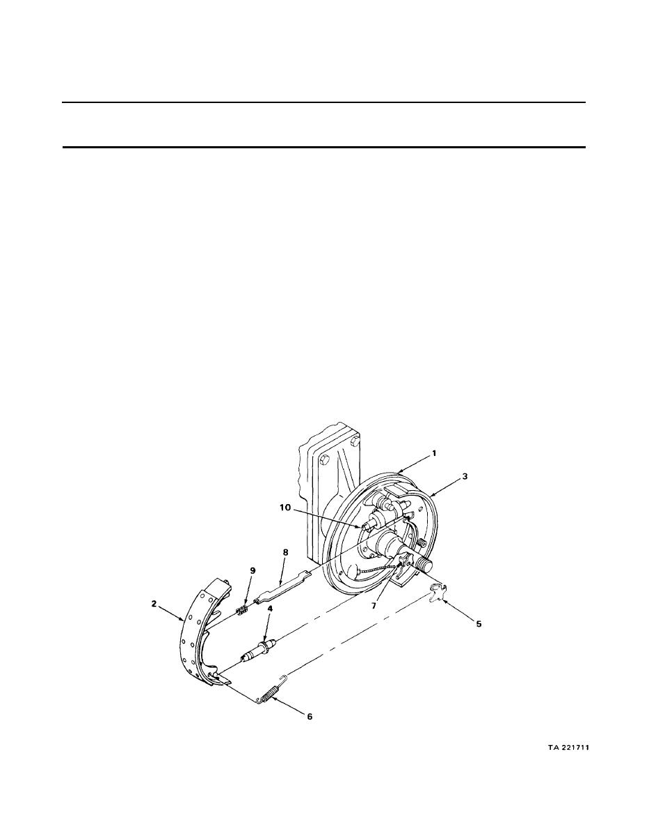
12 Backing plate (1)
Front shoe (2),
a. Hook lever (5) into rear shoe (3).
rear shoe (3),
b. Hook spring (6) between lever (5) and
front shoe (2).
adjuster assembly
(4), lever (5)
c. Spread shoes (2) and (3) apart at the
bottom far enough to insert adjuster
and spring (6)
assembly (4).
NOTE
Step 13 should be omitted if the front dolly service brakes
are being worked on.
13
Lever (7) and
Strut (8) and
a. Place spring (9) over end of strut (8).
front shoe (2)
spring (9)
b. Position parts between lever (7) and
front shoe (8).
c. Hook shoes (2) and (3) into two wheel
cylinder links (10).
4-100

