
TM 9-2330-356-14
(3) Ensure that all valves are closed.
bottom load adapter and connect underwing nozzle
(4) Connect ground wire to storage facility and
semitrailer (fig. 2-7). Remove 4-inch bulk fuel hose
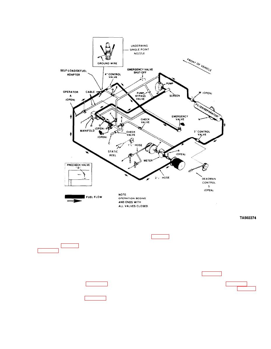
NOTE
facility. Remove dust cap from outlet B and connect bulk
Make sure valve E is closed and remains
fuel hose to outlet.
closed during entire self-load operation.
(5) Remove fire extinguishers and bring to point
(8) Open valves A (para 2-11f), B, G, M, and R.
of operation.
(9) Unreel deadman control S (para 2-11) and
(6) Start engine (para 2-10) and when warm
squeeze the lever. Meter inlet pressure gage (fig. 2-15)
adjust engine speed to 10001200 rpm.
should read a minimum of 25 psi. Release the deadman
(7) Release lock (para 2-11c) on 2-inch hose
control. Should gage not indicate a minimum of 25 psi,
shut down operation and contact unit maintenance.
reel. Unreel 2-inch hose fully. Remove dust cap from
2-37

