
TM 9-2330-357-14&P
4-24. UPPER OUTRIGGER LIMIT SWITCH MAINTENANCE (Con't).
2.
Inspect for loose, missing, or damaged hardware.
3.
Inspect wiring for damage, deteriorated insulation, and broken or frayed conductors.
4.
Inspect upper outrigger limit switch for cracks or signs of burning.
5.
Inspect bracket for cracks, rust, or corrosion.
c. INSTALLATION
1.
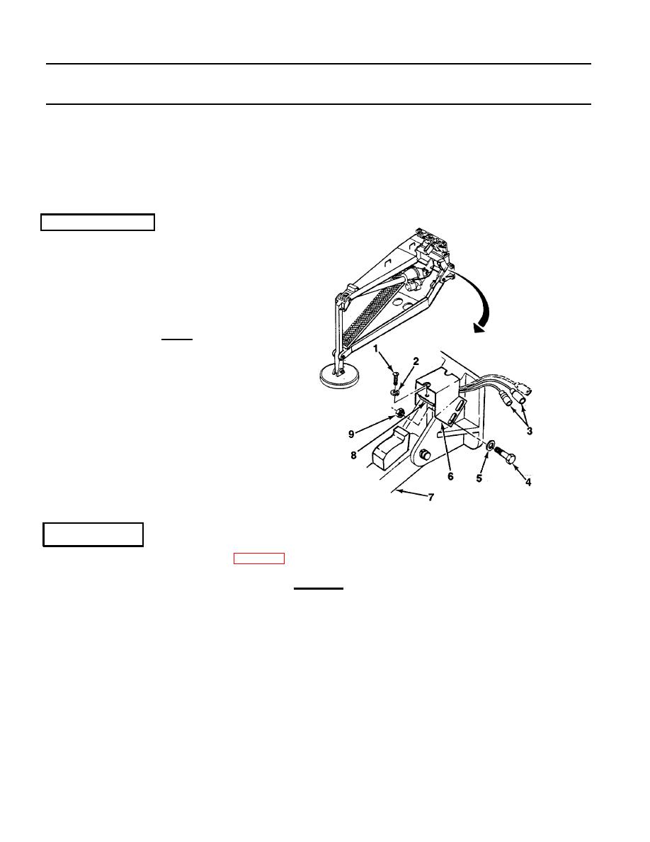
Install upper outrigger limit switch (8) into
bracket (6) with two new lockwashers (2) and
screws (1).
2.
Install bracket (6) to outrigger (7) with two
washers (5), screws (4), and new locknuts (9).
_____
NOTE
Unused lead and connector of upper outrigger
limit switch must be folded and safely bound to
other leads using electrical tape.
3.
Connect two switch connectors (3) to harness
connectors.
d. ADJUSTMENT
1.
Raise all outriggers off ground (para 2-12).
CAUTION
Ensure that there is no interference or forcing of outriggers beyond their limits. Adjust upper
outrigger limit switch mounting bracket and/or upper outrigger limit switch so that plunger on switch
is depressed to activate switch. Failure to do so will result in improper adjustment.
Outside width between right front and left front or right rear and left rear outrigger should be no
greater than 9 ft 10 in. (3 m). If measurement is incorrect, damage to equipment may result.
TA706449
4-34

