
TM 9-2330-381-14
4-22.
GOOSENECK COMPONENT ASSEMBLY (CONT)
11.
Aline and install fixed resistor R3 (8) to gooseneck component assembly (4) and secure with two screws (6) and
locknuts (5).
12.
Using semitrailer electrical schematic (figure FO-1) as a guide, connect a point-to-point jumper wire from terminal
board TB2 (12) to fixed resistor R2 (3).
13.
Aline and install fixed resistor R2 (3) to gooseneck component assembly (4) and secure with four screws (2) and
locknuts (1).
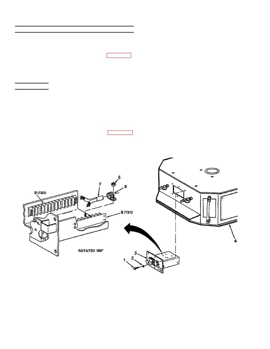
INSTALLATION
NOTE
Reinstall gooseneck component assembly upside down at first into gooseneck so
that the W1 harness can be reconnected to terminal boards TB1 and TB2.
1.
Aline and install gooseneck component assembly (3) upside down and partially into gooseneck (4).
2.
Using semitrailer electrical schematic (figure FO-1) as a guide, reconnect W1 harness (7) to B side of terminal
boards TB1 (8) and TB2 (9).
4-100

