
TM 9-2330-384-14&P
4-72. PRECHECK SYSTEM MAINTENANCE (Con't).
(26) Loosen nut (20) and disconnect tubing (21) from elbow (19).
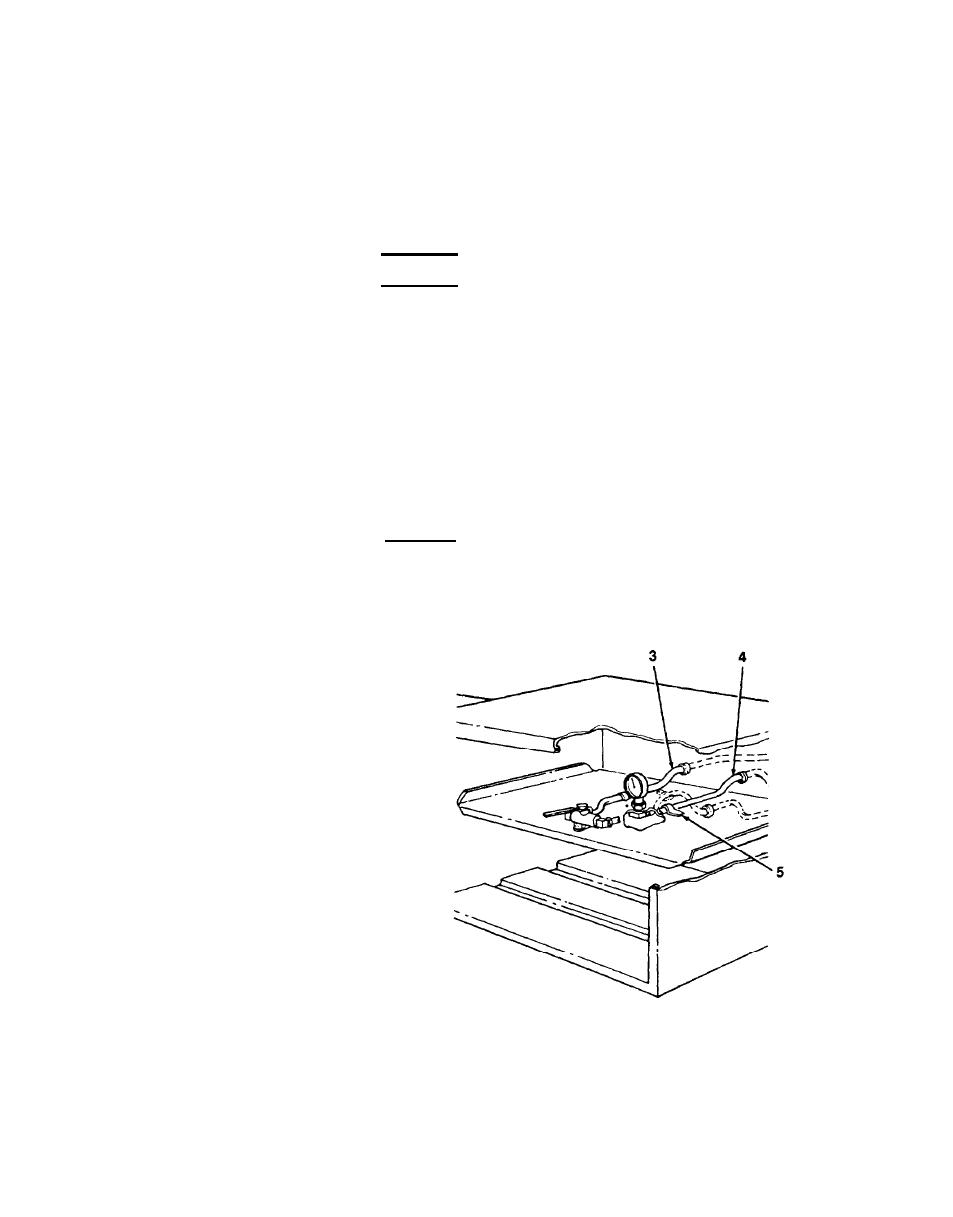
(27) Release tubing (21) from under all clips (5) inside tank and remove.
h. INSTALLATION OF PRECHECK TUBING
WARNING
When working inside tank, always provide adequate forced air ventilation
l
at the manhole opening with air directed into compartment where work
is being performed. Forced air ventilation allows for removal of any ex-
plosive quantities and contaminants resulting from the type of work be-
ing done, and serves to prevent oxygen deficiency. Failure to follow this
warning may result in death to personnel.
NEVER work alone inside a tank: a second person must be stationed at
l
the manhole opening. The person inside the tank must have a safety line
and harness on in case of emergency for rescue operations. In the event
a rescue operation is required, summon assistance IMMEDIATELY. DO
NOT attempt a rescue until assistance has arrived.
CAUTION
Use caution when securing tubing under clips (5). Improper handling of
clips will cause them to break.
NOTE
All male threads of all fittings
l
should be coated with antiseize
tape if not already factory-coated
with an antiseize compound.
For information on manufacturing
l
tubing lengths, refer to Appen-
dix G.
To install tubing (21), perform
l
steps 1 through 3.
To install tubing (14), perform
l
steps 4 through 9.
To install tubing (4), perform
l
steps 10 through 15.
To install tubing (3), perform
l
steps 18 through 21.
(1) Position tubing (21) inside tank
between jet level sensor and
check valve (26). Allow slack in
tubing at each end. Secure tubing
with clips (5). Use a soft-faced
hammer to gently tap clips back
into position.
4-234

