
TM 9-2330-386-14&P
4-22 WIRE CONNECTORS (CONT) .
(10) Apply insulating compound to outside of female connector shell. Push
c o n n e c t o r halves together until seated.
(11) Connect power. T e s t semitrailer lights for proper operation.
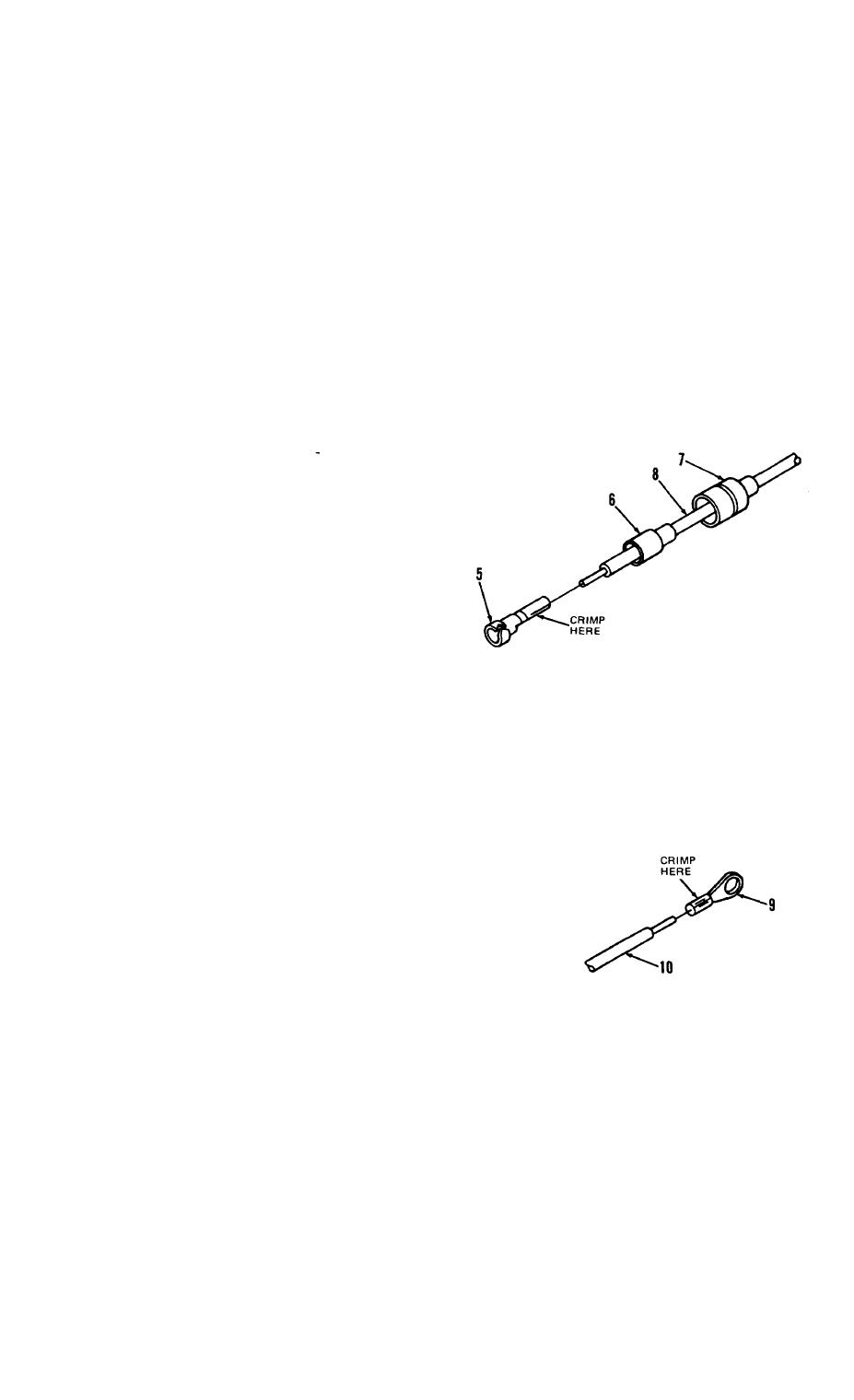
b.Female
Connector
Repair.
( 1 ) Slide shell (7) and insulator ( 6 ) up wire lead (8) until clear of
t e r m i n a l (5).
(2) Cut wire lead (8) as close as p o s s i b l e to terminal (5).
( 3 ) S l i d e i n s u l a t o r (6) and shell ( 7 ) off wire lead (8).
(4)
S t r i p i n s u l a t i o n from wire lead (8) l/8-inch from end.
( 5 ) S l i d e s h e l l (7) and insulator (6) on wire lead (8).
( 6 ) S l i d e w i r e lead (8) end in terminal (5). C r i m p terminal to wire lead.
Apply insulating compound to end of wire lead (8).
( 7 ) S l i d e i n s u l a t o r (6) and shell
( 7 ) over terminal (5) until
seated.
( 8 ) Apply insulating compound to
outside of female connector
s h e l l ( 7 ) . P u s h connector halves
together until seated.
( 9 ) Connect power. Test semitrailer
l i g h t s for proper operation.
c. Terminal
Replacement.
NOTE
This procedure is typical for ring-type and quick
d i s c o n n e c t terminals. Procedure shown is for ring
( g r o u n d i n g ) terminal.
Cut wire lead (10) as close as possible to t e r m i n a l ( 9 ) . D i s c a r d
terminal.
(1)
( 2 ) S t r i p insulation from wire lead (10) equal to depth of new terminal (9).
Slide wire lead (10) end in new terminal
(3)
( 9 ) . Crimp texminal to wire lead.
Connect terminal.
(4)
C o n n e c t power. Test semitrailer lights for
(5)
p r o p e r operation.
4-35

