
TM 9-2330-388-14
Section XI. MAINTENANCE OF ENGINE AND PUMP
4-25.
Water Dispensing
Unit
Engine
Throttle
NOTE
Adjustments
Throttle Inspection If the pump is not providing
a.
Air leaks on the suction side of the
high enough pressure, the throttle cable may need
pump will cause high engine speed in
adjustment. When throttle is properly adjusted, control
relation to pump pressure. They will
panel lever should have a springy feel when pushed a
also cause a ragged stream and an
the way to the fast position. The throttle linkage should
Irregular pulsation of the suction and
hit the stop inside the engine before the lever contacts
discharge hose.
the stop on the lever assembly (inner cable tightly
stretched). If this is not so, engine may not be at fu
4-26.
Water Dispensing Unit
Removal
and
throttle even though lever is pushed all the way forward.
Installation from Tanker
WARNING
Wash oil or fuel from skin as soon as
possible after contact. Remove or disconnect
battery before working on engine or pump
set. Never disconnect any wire unless the
engine is stopped and all switches are in the
"OFF" position
a.
Removal
1.
Open pump cabinet door.
2.
Remove six screws attaching rear panel to
cabinet.
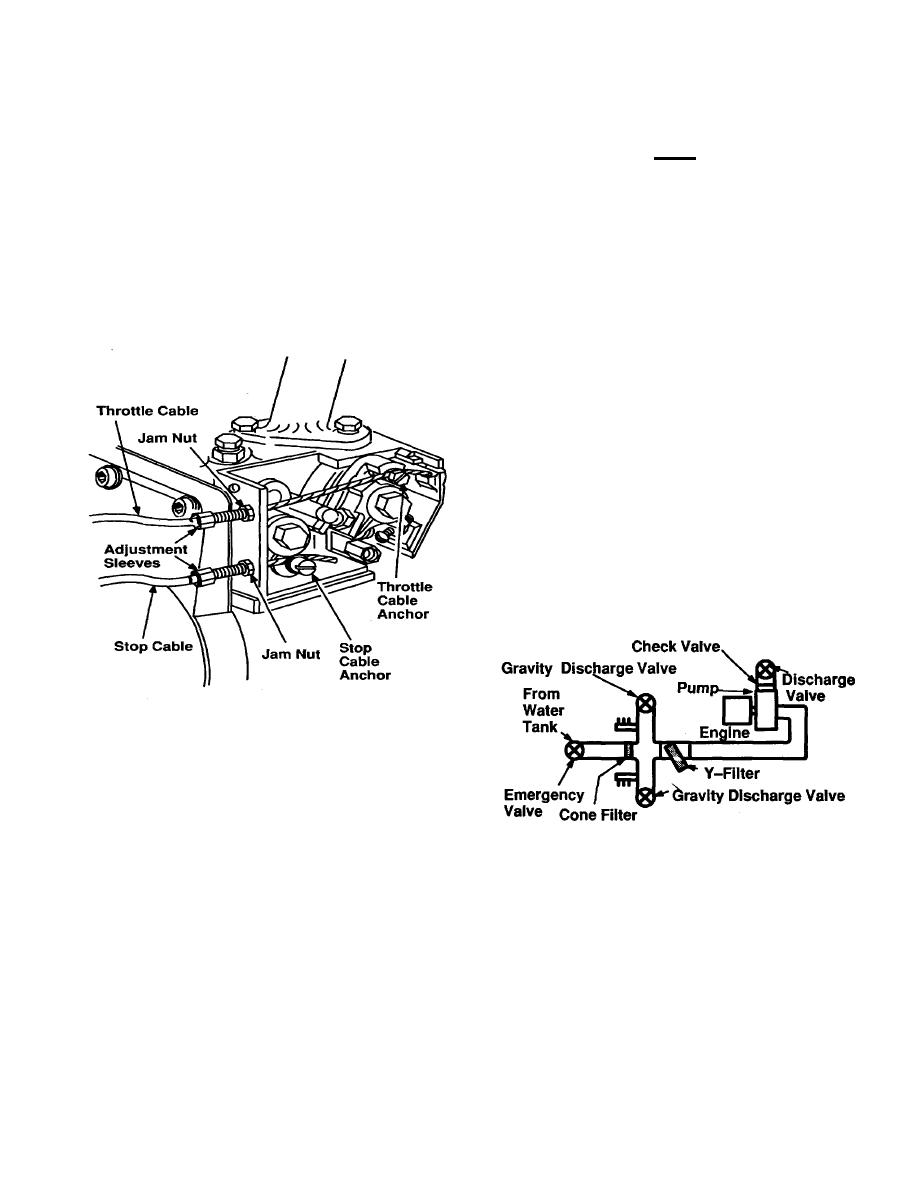
Figure 4-24. Throttle and Stop Lever Adjustments
Throttle Adjustment There are two threaded
b.
adjustment sleeves where the throttle and stop cables go
into the engine; the upper one is for the throttle. Loose
the jam nut on the sleeve that is up against the engine
housing. Then turn the adjustment sleeve counter
clockwise a couple of turns.
Holding the sleeve,
Figure 4-25. M1098 Water Dispensing Schematic
retighten the jam nut. This should make the inner cable
tight when the panel lever is turned fully counter clock-
3.
Close emergency valve and open discharge
wise to tighten inner cable and clockwise to loosen it.
valve to drain water from pump and water pipes.
Stop Adjustment The stop cable (lower cable)
c.
can be adjusted in a similar manner to the throttle cable.
4-88

