
TM 9-2330-388-14
(5) Loosen three set screws (12) and remove
(2) Install 0-ring (5) and two packing glands (6)
bonnet (13).
into stuffing box nut (4). Install stuffing box nut fly sliding
(6) Remove spring (14), then pull stem (1 along
over stem (7), and screw into body.
with assembled disc assembly, out through top of valve.
(3) Install lever (1) onto stem (7) and tighten
(7) Remove nut (16), washer (17), retaining
screw (2) and nut (3).
plate (18), plunger disc (19), and disc holder (20) from
(4) Install disc holder (20), plunger disc (19),
stem (15).
retaining plate (18) and washer (17) onto stem (15).
Install and tighten nut (16).
(5) Install assembled stem and disc into top of
body. Install spring (14).
(6) Install bonnet (13) and secure in place by
tightening three set screws (12).
(7) Install adapter (11), and tighten set screw
(10) to secure adapter to stem (15).
4-32.
Draining Pump
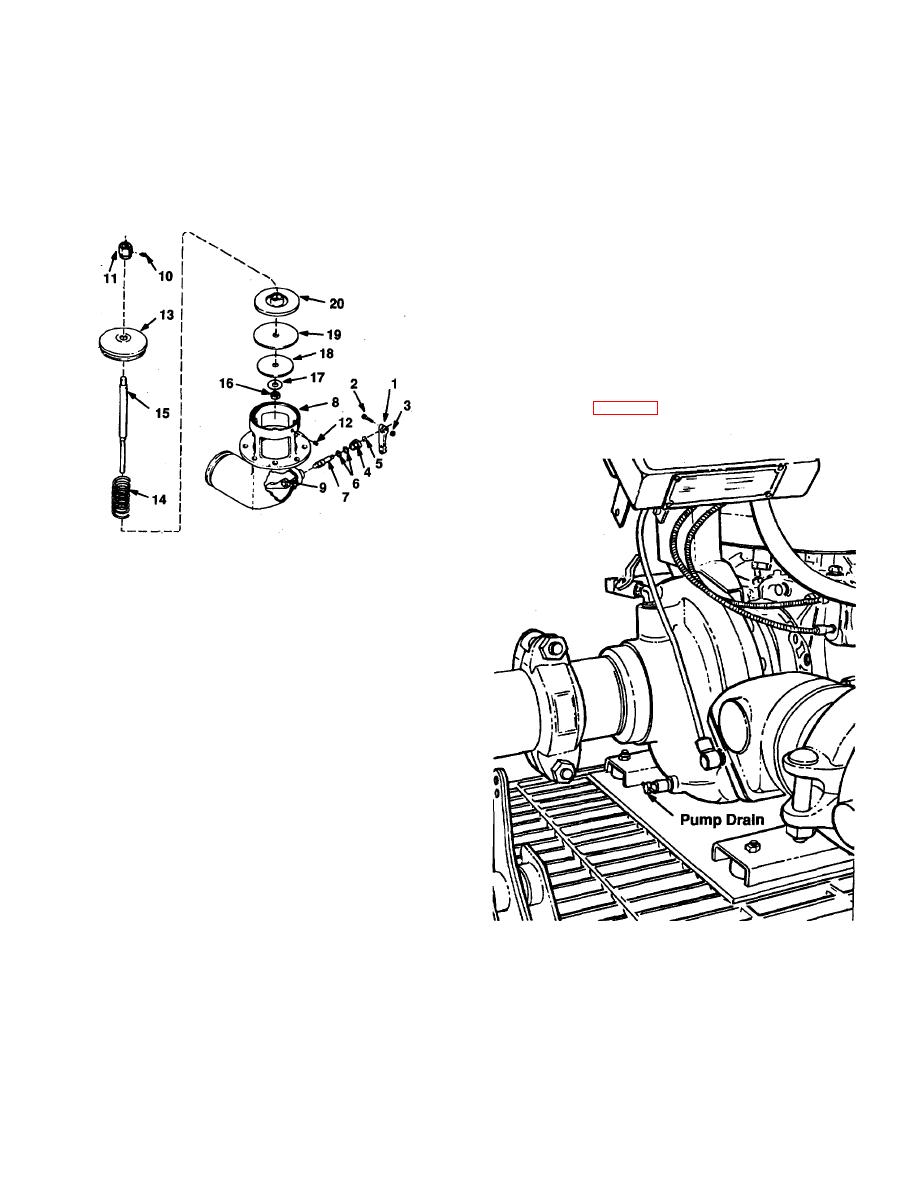
The pump is drained through the discharge valve
and drain valve, fig. 4-33.
1.
Lever
11.
Adapter
2.
Screw
12.
Set Screw
3.
Nut
13.
Bonnet
4.
Stuffing Box Nut
14.
Spring
5.
O-ring
15.
Stem
6.
Packing Glands (2)
16.
Nut
7.
Stem
17.
Washer
8.
Body
18.
Retaining Plate
9.
Cam
19.
Plunger Disc
10.
Set Screw
20.
Holder
Figure 4-32. Emergency Valve Disassembled
b.
Cleaning and Inspection.
(1) Clean all metal parts and dry thoroughly.
(2) Replace gaskets. Inspect valve for cracks,
distortion, and wear. Inspect all parts for damage and
replace any damaged part.
c.
Assembly.
(1) Position cam (9) inside the body (8), and
Figure 4-33. Pump Drain
install stem (7) into body.
4-93

