
TM 9-2330-388-14
4-42.
Brake Air Chamber Test and Replacement of
b.
Removal.
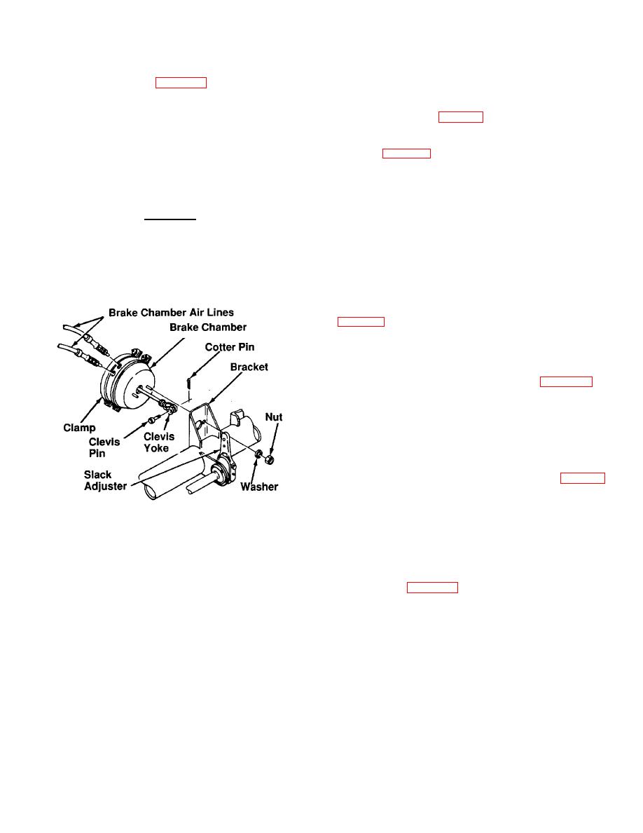
Brake Chamber, Fig. 4-48.
(1) Open drain valves on the air reservoirs and
a.
Test.
allow air to bleed off, fig. 4-54.
(1) With towing vehicle connected and vehicle
(2) Disconnect two brake hoses from brake
brakes applied, coat the flanges and connections on the
chamber, fig. 4-48.
air chamber with soapy water.
(3) Remove cotter pin and clevis pin securing
(2) Check for leakage indicated by bubbles.
clevis yoke to slack adjuster.
No leakage is permissible.
(4) Remove two nuts, two lockwashers
WARNING
securing brake chamber to bracket.
Discard
lockwashers.
DO NOT overtighten clamp on air chamber.
Maximum torque should be 20-25 lb-ft Over-
(5) Remove brake chamber.
tightening will distort the flange and cause
more leakage.
d.
Installation
(1) Place brake chamber in position on bracket,
(2) Install two new lockwashers and two nuts to
secure brake chamber to bracket.
(3) Check clevis yoke adjustment, para 4-41.
(4) Install clevis pin and cotter pin to secure
yoke to slack adjuster.
(5) Connect
two
brake
hoses
to
brake
chamber.
(6) Close drain valves on air reservoirs, fig. 4-
54.
(7) Pressurize air brake system and check for
Figure 4-48. Removing and Installing Brake Chamber
leaks.
(3) If leakage is found at flange, tighten the
WARNING
clamp. If leakage is found at connections, tighten
fittings.
DO NOT attempt to repair brake chamber fail-
safe unit, Fig. 4-49. It is dangerous since the
(4) After initial brake application forced out a
spring Is highly compressed. No repair Is
small amount of air, no air should he expelled from the
authorized for fail-safe unit.
air chamber. If air continued to exhaust, replacement of
the brake chamber and fail-safe unit as an assembly is
necessary.
4-112

