

Custom Search
|
|

|
||
 TM 9-2330-394-13&P
ELECTRICAL SYSTEM TROUBLESHOOTING - Continued
0036 00
ELECTRICAL SYSTEM - Continued
Table 1. Electrical System Troubleshooting Procedures - Continued
MALFUNCTION
TEST OR INSPECTION
CORRECTIVE ACTION
2.
ONE OR MORE REAR
4.
Connect negative (-) probe
MARKER LIGHTS DO NOT
of digital multimeter to side
ILLUMINATE - CONTINUED
of socket side of lamp.
5.
Note reading on digital
multimeter.
6.
If continuity is not present,
replace right rear marker
lamp (WP 0050 00).
3.
Check for continuity between
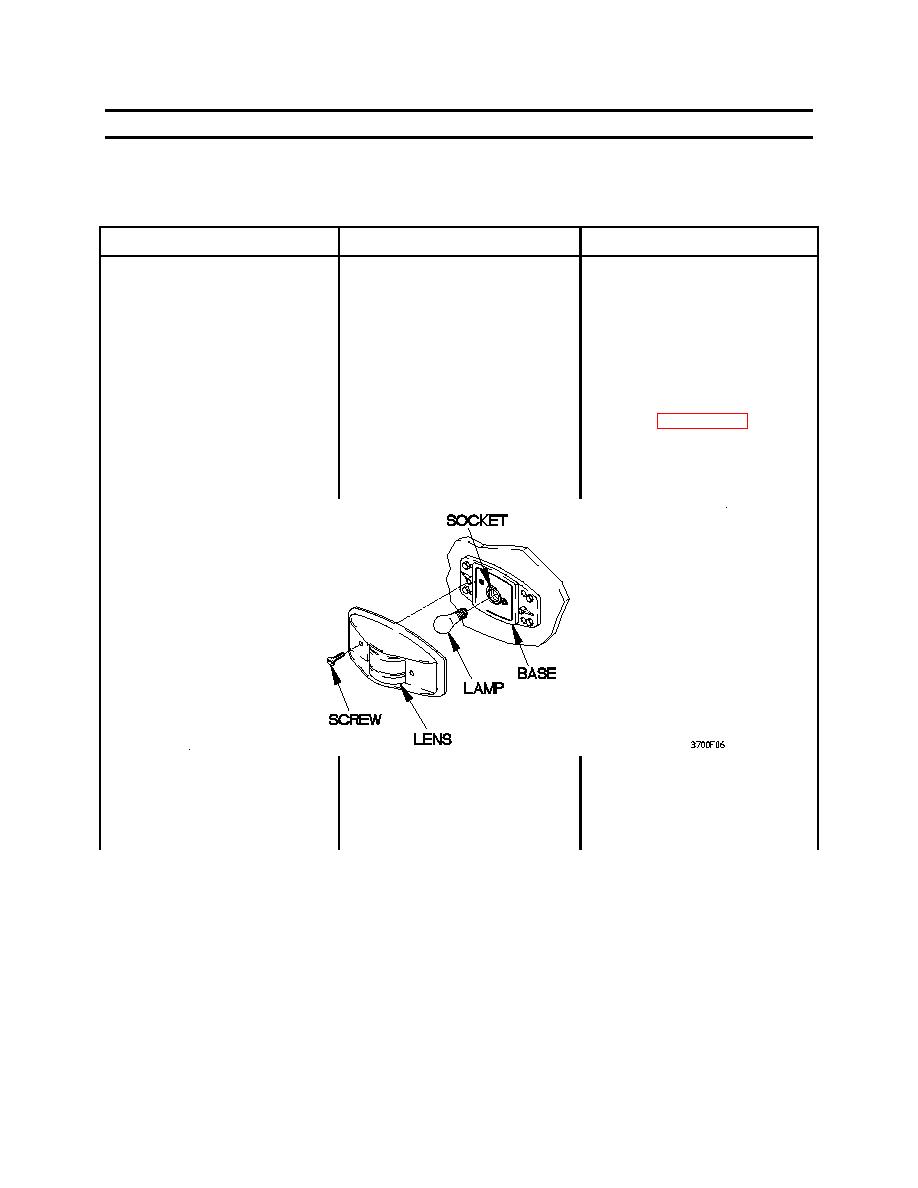
1.
Install right rear marker
terminal lug TL266 and
lamp in socket.
terminal lug TL261.
2.
Install lens on base with two
screws.
3.
Set digital multimeter to
ohms.
0036 00-6
|
||
|
||


