

Custom Search
|
|

|
||
 TM 9-2330-394-13&P
ELECTRICAL SYSTEM TROUBLESHOOTING - Continued
0036 00
ELECTRICAL SYSTEM - Continued
Table 1. Electrical System Troubleshooting Procedures - Continued
MALFUNCTION
TEST OR INSPECTION
CORRECTIVE ACTION
3.
RIGHT FRONT MARKER
6.
If 8-14 vdc is not present,
LIGHT DOES NOT
go to Test Or Inspection
ILLUMINATE - CONTINUED
number 7 of this
Malfunction. If 8-14 vdc is
present go to (Test Or
Inspection) number 8 of
this Malfunction.
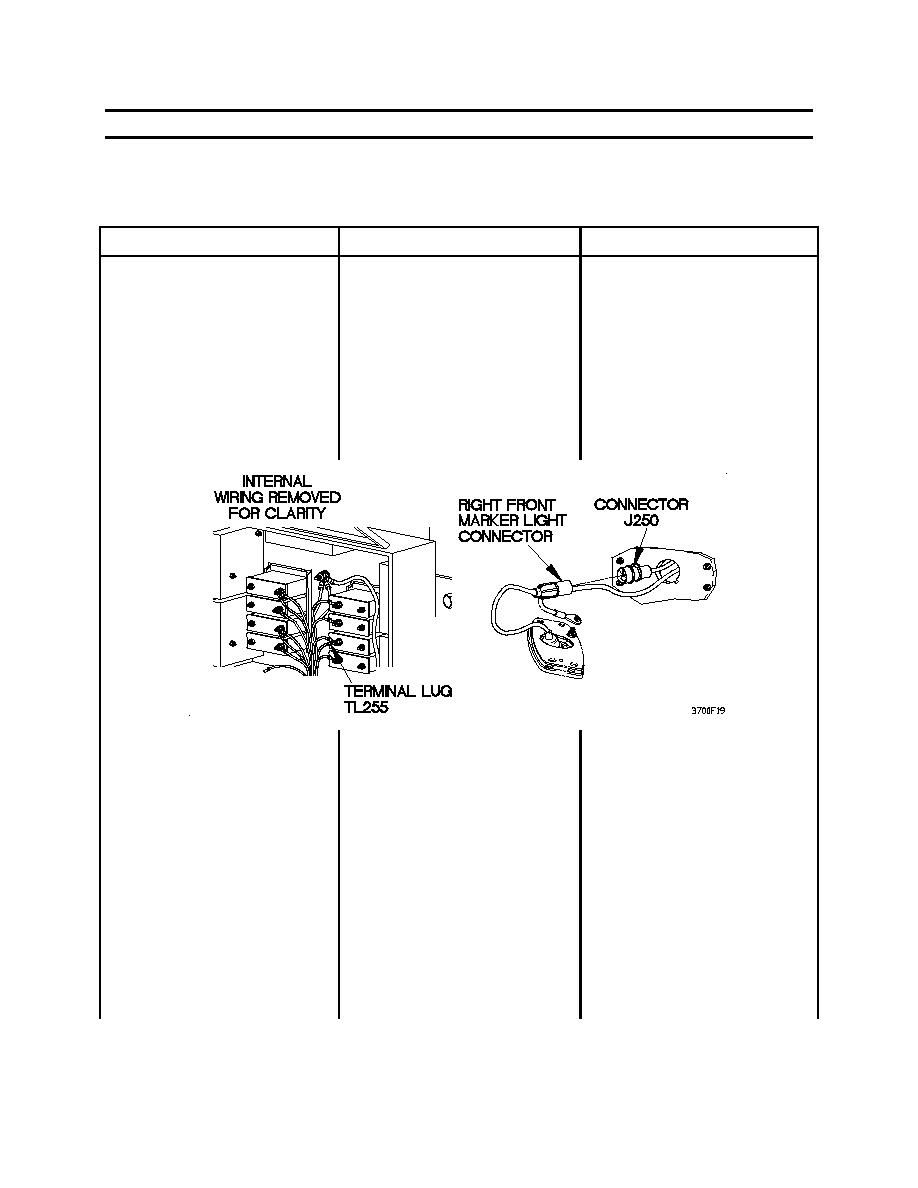
6.
Check for continuity
1.
Position towing vehicle main
between connector J250 and
light switch to OFF.
terminal lug TL255.
2.
Disconnect connector J250
from right front marker light
connector.
3.
Set digital multimeter to
ohms.
4.
Connect positive (+) probe
of digital multimeter to
connector J250.
5.
Connect negative (-) probe
of digital multimeter to
terminal lug TL255.
6.
Note reading on digital
multimeter.
0036 00-20
|
||
|
||


