


Custom Search
|
|

|
||
 TM 9-2330-394-13&P
ELECTRICAL SYSTEM TROUBLESHOOTING - Continued
0036 00
ELECTRICAL SYSTEM - Continued
Table 1. Electrical System Troubleshooting Procedures - Continued
MALFUNCTION
TEST OR INSPECTION
CORRECTIVE ACTION
7.
RIGHT STOPLIGHT DOES
2.
Connect positive (+) probe
NOT ILLUMINATE -
of digital multimeter to 24
CONTINUED
vdc intervehicular cable
connector pin J.
3.
Connect negative (-) probe
of digital multimeter to a
known good ground.
4.
Position towing vehicle main
light switch to STOPLIGHT
and note reading on digital
multimeter.
5.
If continuity is not present,
replace 24 vdc intervehicular
cable.
6.
Position towing vehicle main
light switch to OFF.
2.
Check continuity across
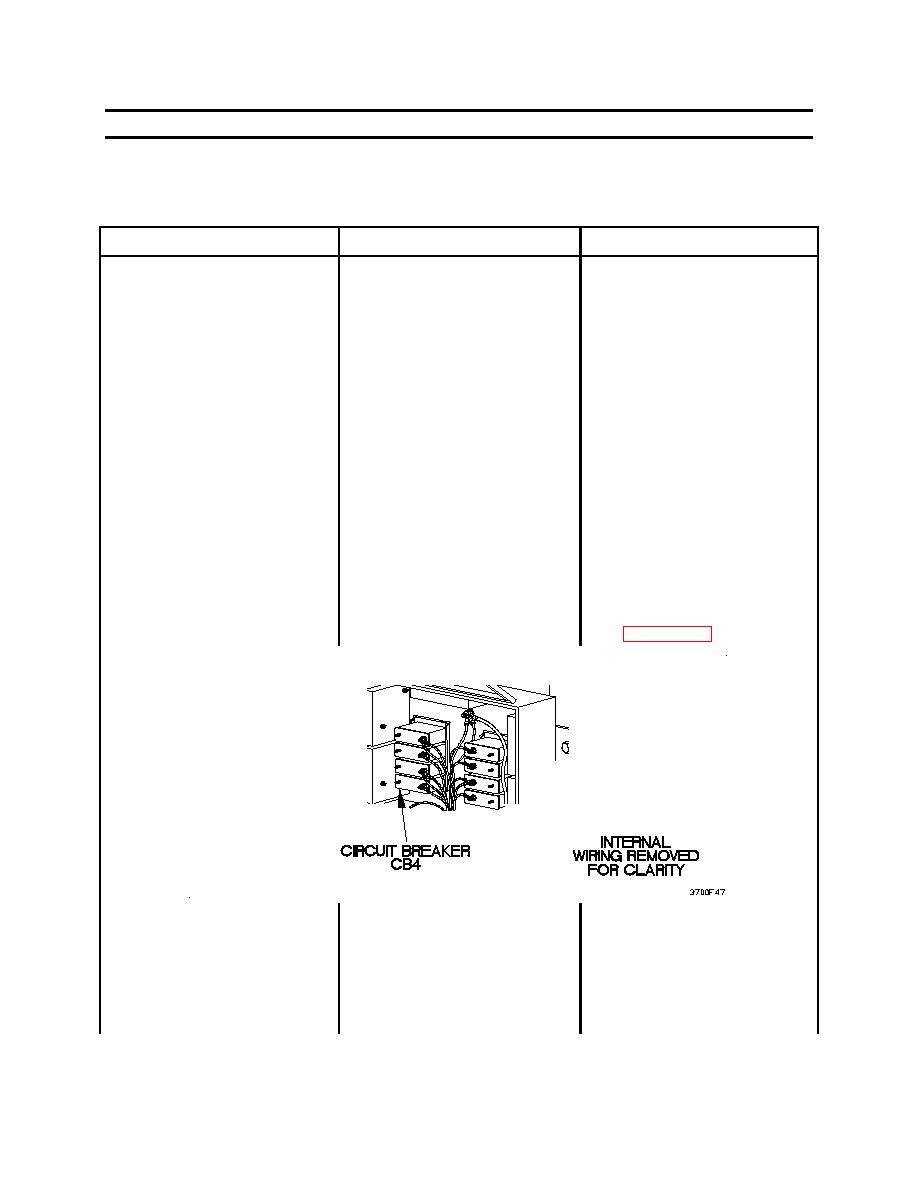
1.
Open voltage converter box
circuit breaker CB4.
2.
Set digital multimeter to
ohms.
3.
Connect positive (+) probe
of digital multimeter to one
terminal of circuit breaker
CB4.
0036 00-46
|
||
|
||
|
|
Integrated Publishing, Inc. - A (SDVOSB) Service Disabled Veteran Owned Small Business
|


