

Custom Search
|
|
|
|
||

|
||
 TM 9-2330-394-13&P
BRAKE SYSTEM TROUBLESHOOTING - Continued
0037 00
BRAKE SYSTEM - Continued
Table 1. Brake System Troubleshooting Procedures - Continued.
MALFUNCTION
TEST OR INSPECTION
CORRECTIVE ACTION
2.
Check to see if continuity is
1.
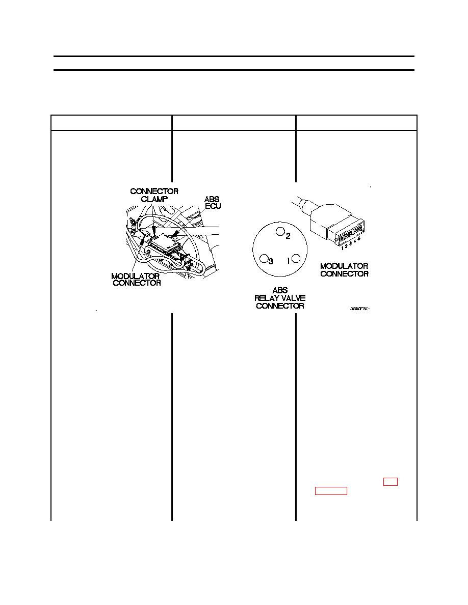
Disconnect MODULATOR
13. ANTI-LOCK BRAKING
present across ABS ECU valve
connector from ABS ECU.
SYSTEM (ABS) DIAGNOSTIC
to relay valve harness, pins 1
TOOL BLINKS NINE TIMES IN
and 2.
SERIES: ABS RELAY VALVE
FAULT - CONTINUED
2.
Install jumper wire across
pins 1 and 2 on
MODULATOR connector.
3.
Set digital multimeter to
ohms.
4.
Connect positive (+) probe
of digital multimeter to relay
valve connector pin 1.
5.
Connect negative (-) probe
of digital multimeter to relay
valve connector pin 2 and
note reading on digital
multimeter.
6.
If continuity is not present,
replace ABS ECU valve to
relay valve harness (WP
7.
Remove jumper wire from
MODULATOR connector.
0037 00-57
|
||
|
||


