

Custom Search
|
|
|
|
||

|
||
 TM 9-2330-394-13&P
BRAKE SYSTEM TROUBLESHOOTING - Continued
0037 00
BRAKE SYSTEM - Continued
Table 1. Brake System Troubleshooting Procedures - Continued.
MALFUNCTION
TEST OR INSPECTION
CORRECTIVE ACTION
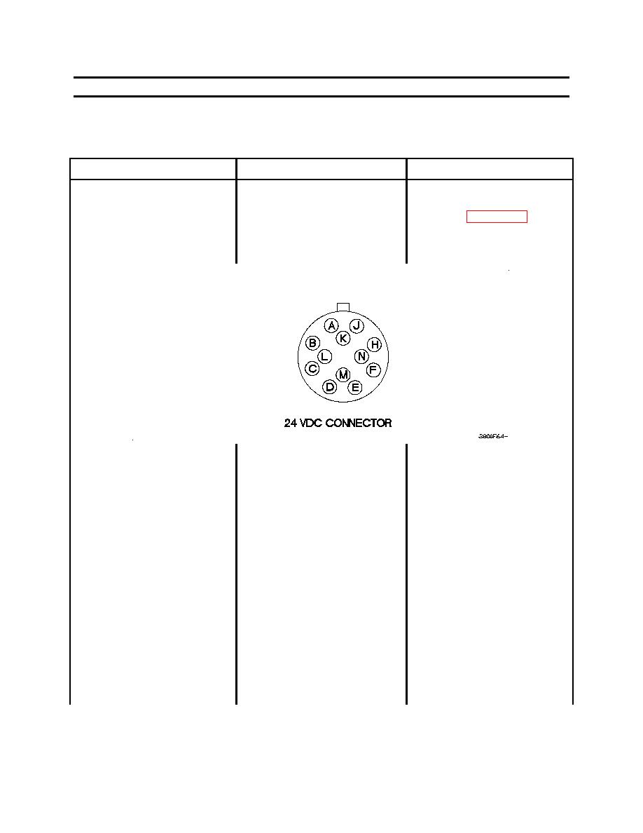
4.
Check to see if 18-26 vdc is
1.
Disconnect 24 vdc
15. ANTI-LOCK BRAKING
present at 24 vdc
intervehicular cable from
SYSTEM (ABS) DIAGNOSTIC
intervehicular cable connector
trailer (WP 0012 00).
TOOL BLINKS 14 TIMES IN
pin K.
SERIES: ABS SYSTEM
CONFIGURATION OR POWER
SUPPLY FAULT - CONTINUED
2.
Set digital multimeter to
ohms.
3.
Connect positive (+) of
digital multimeter to 24 vdc
intervehicular cable
connector pin K.
4.
Connect negative (-)of
digital multimeter to a
known good ground.
5.
Start towing vehicle engine.
6.
If towing vehicle is not FMTV
A1, position main light
switch to SER DRIVE and
depress brake pedal during
step (7).
7.
Note reading on digital
multimeter.
0037 00-72
|
||
|
||


