

Custom Search
|
|

|
||
 TM 9-2330-394-13&P
MECHANICAL STOP AND RESILIENT MOUNT REPLACEMENT
0076 00
- Continued
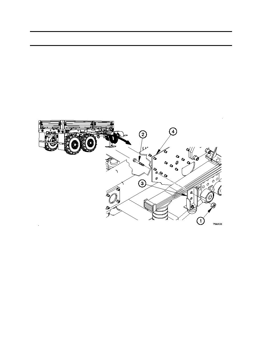
MECHANICAL STOP INSTALLATION, MTVT
NOTE
All mechanical stops are installed the same way. Right side front shown.
1.
Position mechanical stop (3) on frame plate (4) with two bolts (2) and self-locking nuts (1).
Tighten two self-locking nuts (1) to 148-185 lb-ft (200-250 Nm).
2.
0076 00-3
|
||
|
||


