
TM 9-2330-398-10
2-2. ENGINE CONTROL PANEL.
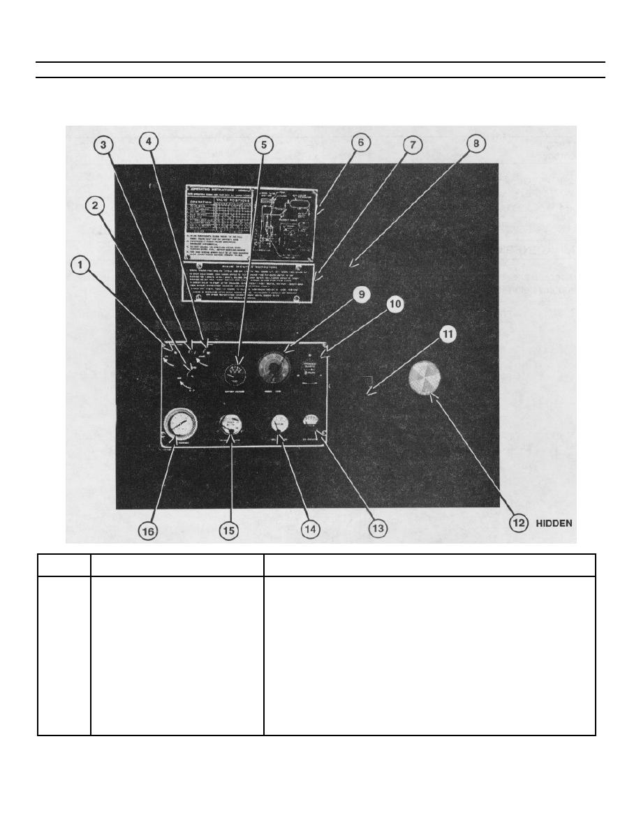
The engine control panel is located on the road side of the semitrailer, above the piping assembly. Control functions and
gage readings are explained in the table that follows the illustration.
KEY
COMPONENT
DESCRIPTION
1
Preheater Switch
Connects battery voltage to glow plugs in engine
intake manifold to preheat the engine. (Engine
switch. item 2, must he in RUN position.)
2
Engine Switch
In RUN position, energizes engine electrical
system and fuel pumps to permit engine operation.
STOP position cuts off fuel supply and stops the engine.
3
Indicator Light
This should turn on when preheater switch, item 1, is
turned to ON position. If light does not come on, it indi-
cates there is no current flow to the manifold heaters and
glow plugs
2-2

