
TM 9-2590-209-14&P
(3) Remove cotter pin and clevis pin (view A).
(6) Install yoke assembly and secure with
screw, lockwasher, and nut (view A). Adjust clutch
(4) Remove yoke assembly (view A).
control as required (para 10-30).
(5) Remove nut securing rod end bearing
(7) Install transmission shroud, and close rear
from support bracket (view B).
grille doors. See TM 9-2350-21520 (M60O, M60A1),
TM 9-2350-257-20-1 (M60A1 RISE), or TM 9-2350-253-
(6) Remove two screws and lockwashers
20-1 (M60A3).
securing support bracket to right angle drive (view B).
10-29. Maintenance of Mechanical Clutch Control
(7) Remove support bracket (view B).
Assembly.
b. Installation (Fig 10-18).
a. Removal (Fig 10-19).
(1) Install support bracket (view B).
NOTE
(2) Install support bracket to right angle drive,
If cable is removed power plant must be removed to gain
and secure with two screws and lockwashers (view B).
access to cable clamps.
(3) Install rod end bearing to support bracket,
(1) Open rear grille doors, and remove
and secure with nut (view B).
transmission shroud. See TM 9-2350-215-20 (M60,
M60A1), TM 9-2350-257-20-1 (M60A1 RISE), or TM 9-
(4) Install yoke assembly (view A).
2350-253-20-1 (M60A3).
(5) Install clevis pin and cotter pin (view A).
(2) Unscrew handle and housing from cable
and bulkhead (view A).
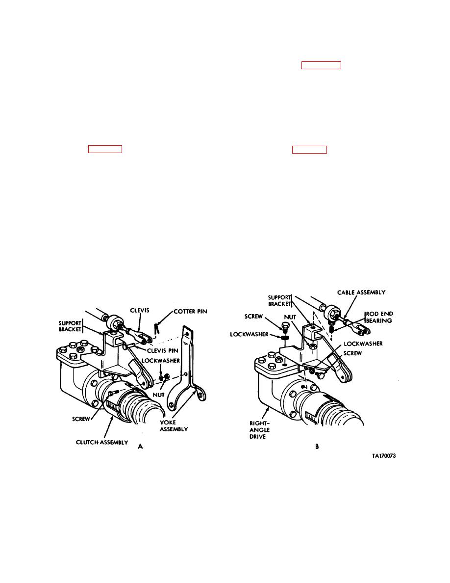
Figure 10-18. Removal or installation of hydraulic mechanical clutch support bracket and yoke assembly.
10-33

