
(4) With control valve handle in stop position, place chain around contour con-
trol sprocket at rear of table, (as shown in sketch) and then loop chain around
two horizontal rollers at ends of guide roller bar.
(5) With guide roller bar in extreme reverse position, take up all slack in chain and
connect ends together, using quick lock provided. The power feed is then
ready for operation.
B. OPERATION
(1) Always be sure there is enough hydraulic oil in tank. Check oil level with dip
nick provided.
(2) Clean tank and oil filter every six months. Oil filter is located inside of tank and
may be serviced by removing cover plate at front end of tank.
(3) If hydraulic pressure drops, dirt may be lodged in relief valve or relief valve spring
may be weak. The relief valve is set at 100 pounds pressure at factory. To in-
crease pressure, remove the cap on top of relief valve and turn adjustment screw
clockwise. Check pressure with a pressure gage. If pressure is high enough and
pulling power is still low, cylinder piston cups may have to be replaced.
(4) If control valve does not operate properly, there may be dirt between disk and
face of valve. If so, valve should be taken apart and faces cleaned or lapped if
necessary.
(5) Bumpy or uneven feed is caused by air in cylinder. This air may be removed by
running piston rod back and forth for full length of cylinder a number of times.
This condition usually occurs when a new machine is installed and started for
first time, or when system has been drained, cleaned and refilled with oil.
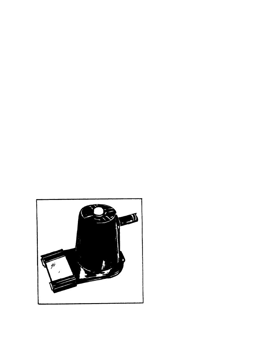
WORK MAGNIFIER
The plastic-constructed magnifier is
light-weight and easily mountable to
the machine's worklamp reflector
with a single locking bolt and nut.
A snap-on protective lens cover
prevents scratching or damage when
the magnifier is not in use.
24

