
TM 9-3405-215-14&P
BAND TRACKING
SPEED CONTROL
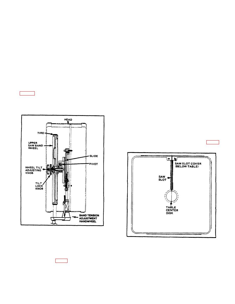
The upper wheel can be tilted forward and backward a
A transmission shift lever selects between two speed
maximum distance of 3 inches (75 mm) to aid band
ranges. Each can be infinitely varied within its range by
tracking. A properly tracking band center should follow
the band speed control located on machine front. Speed
crowned rubber wheel tire centers.
Perform
the
ranges are 50-300 fpm (15-90 m/min) and 850-5200 fpm
following tracking procedures with drive "off" and
(259-1585 m/min). Good practice recommends the
transmission in "neutral".
following operator precautions:
(1) Open band wheel doors. Manually turn wheels and
(1) Before shifting gears: turn band speed control to
observe how band tracks on tires. Adjust wheel tilt if
"TRANS. SHIFT POINT" (this releases the solenoid
band does not track on tire centers.
interlock) and make sure band is stopped. Turn
drive wheel by hand when shifting to engage clutch.
(2) Change wheel tilt by loosening lock nut and
adjusting tilt knob until band rides tire correctly. See
(2) Always turn band speed control to "slow" before
stopping machine.
guide back-up bearings.
(3) Do not attempt to force shift lever into place.
(3) Tighten lock nut.
WORK TABLE
Standard machine work table measures 26 inches (660
mm) by 26 inches (660 mm).
All tables are drilled and tapped on front, rear, and right
edges for accessory attachment. Table center disk is
removable for changing saw bands, and for installing
special-purpose center filing or polishing disks. See Fig. 11.
FIG. 10. WHEEL TILT ADJUSTMENT -SIDE VIEW.
POST ADJUSTMENT
FIG. 11. TYPICAL WORK TABLE - TOP VIEW.
Post elevation is adjusted manually by turning
handwheel located on saw head. Turn wheel clockwise
to lower post and upper saw guide; raise by turning
counter-clockwise. See Fig 9. Always keep post and
upper saw guide as close as possible to workpiece.
Band guards should be locked in place at all times
during sawing.
8

