
With a properly tensioned new blade on the
machine, place the combination square against the
front face of the blade very lightly so the blade will
not be deflected and slide the square against the
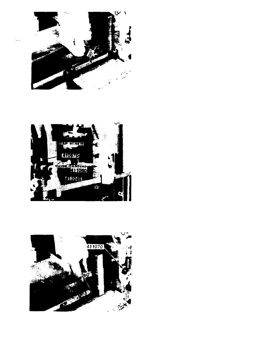
rear vise jaw (Fig. 5). If the blade and vise jaw are
not at right angles, refer to Fig. 6. The cam bolt
410520 on the lower end of each guide arm can be
adjusted to bring the blade into parallel alignment
with the saw bed and at right angles to the work
vise. Loosen the hex head cap screw (Fig. 6 ) and the
hex nut on the 410520 cam bolt. By turning the cam
bolt the lower end of the blade guide casting 411040
or 411060 can be moved in or out to bring the blade
into parallel alignment with the saw bed. The
question at this point is which guide should be
moved in which direction to keep the blade in as
Fig. 5
straight a line as possible between the lower edge of
the two blade carrier wheels. To find out, in-
dividually loosen the hand knob clamps which hold
the guide arms to the guide beam, so that guide
arm movement caused by the tensioned blade may
be observed (Fig. 6, Ref. A & B). Then adjust the
guide castings to minimize this deflection with the
saw bed and at right angles to the work vise. After
retightening the hex nut on the cam bolt and the
hex head cap screw, recheck the blade against the
stationary vise jaw to assure proper alignment is
still intact.
At this point, place the blade gauge furnished with
the machine on the saw blade (Fig. 7) adjacent to
the stationary vise jaw and lower the cutting head
until the cutting edge of the blade is near the work
bed top. Place the combination square blade across
the bed top and move the base of the square against
the face of the blade gauge. If the gauge is not in
vertical alignment with the square an adjustment
Fig. 6
can be made with blade screw 411070 (Fig. 7).
Turn the adjusting screw clockwise to cause the top
end of the blade gauge to move away from the vise
jaw or turn the screw counterclockwise to cause the
top end of the blade gauge to move towards the vise
jaw. After this has bean done on the guide arm
adjacent to the stationary vise jaw, repeat the
operation on the guide arm adjacent to the
moveable vise jaw. If a large correction must be
made on the second guide arm, recheck the setting
of the first guide arm. If large corrections are made
alternately, check and adjust each guide arm as
necessary until the blade at either guide arm is in a
true vertical position.
B. METERING VALVE ADJUSTMENT,
TYPE 010660, MODEL W-9 MACHINES
ONLY.
This is an extremely simple adjustment to make,
yet is the one that creates the most problems.
Fig. 7
37

