
piece of straight shafting about eight inches long into collet
of work-head. The shaft should be true and at least 1/2" In
diameter. Lock shaft in place by tightening collet draw
knob (dia No. 8). A dial indicator should be mounted as
rubbing against the shaft in the collet head, traverse table
back and forth. Adjust until table can be traversed back
and forth at least four inches and a dial indicator reading of
not more than (.004) four thousandth of an inch difference
is achieved. Lock hex nut (dia No. 40 of exploded view
aligning shaft is horizontal.
ILLUSTRATION NO. 2
LINING UP THE WORK-HEAD
3. Repeat steps in paragraph 2. Adjust stop screw No.
38 if necessary.
4. After you have the work-head aligned, move stop pin,
(dia No. 44) to hole at left side of work-head base plate.
stop screw (dia No. 38 of exploded view No.. 3) until a dial
Indicator reading of .002 Is achieved. Lock jam nut (dia
No. 39). Now rotate work-head angle
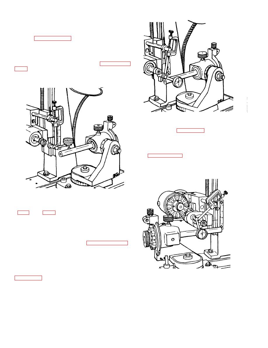
ILLUSTRATION NO. 1
LINING UP THE WORK-HEAD
2. The next step is to reposition dial indicator as shown
the grinder table. Using the same 8" piece shafting,
traverse table back and forth until dial indicator reading of
not more than (.002) two thousand of an inch difference is
read. Rotate work-head and bracket as needed to
accomplish indicator reading. Now set stop screw (dia No.
38) and lock jam nut (dia No. 39 of exploded view No. 3).
You should now be able to loosen angle bracket lock
screw, rotate angle brack slightly, reposition angle bracket
against stop pin (dia No. 44,) lock angle bracket and
traverse table back and forth and have dial indicator read
within .002 Inches. Re-adjust stop screw (dia No. 38) if
ILLUSTRATION NO. 3
you do not get a .002 Inch reading. Repeat check in
LINING UP THE WORK-HEAD
necessary.
3

