
GEAR DRIVE ASSEMBLY
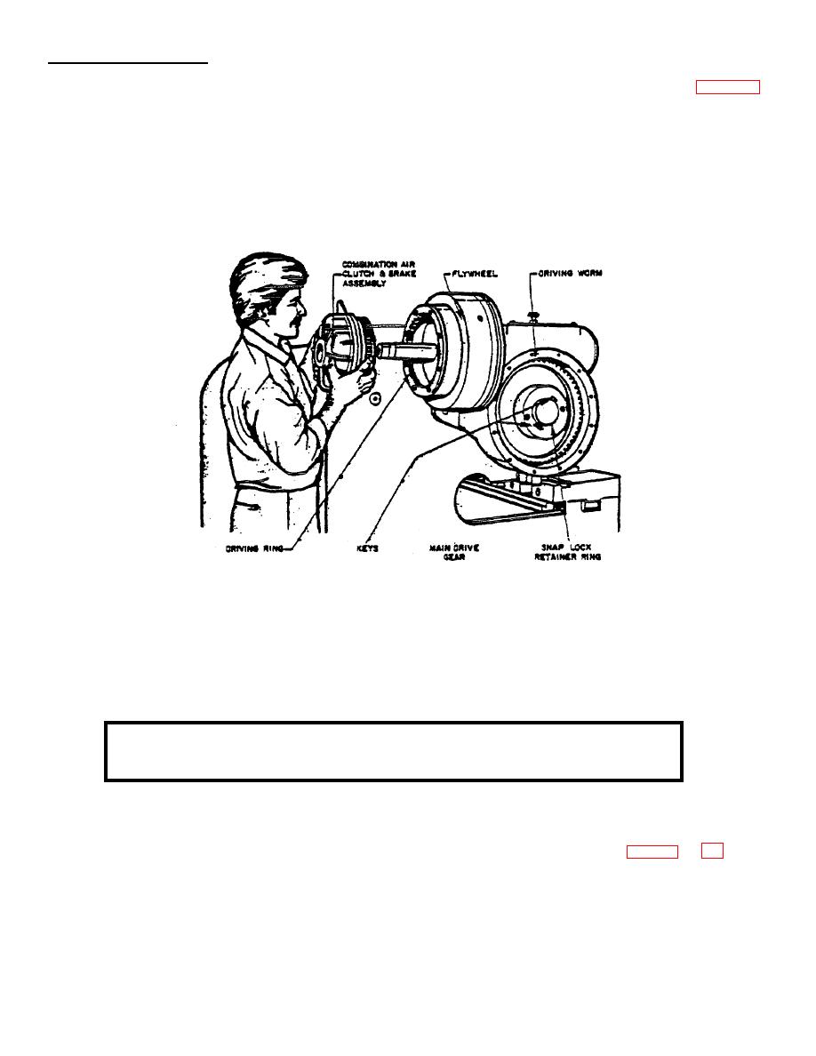
The Gear Drive Assembly for the shear is designed to provide maximum life with minimum maintenance (Figure 31).
Because of the method mounting the Combination Air Clutch and Brakes on the shear, the useful life of the gear train
is materially increased over the type of drive used on other makes of shears. This is true because there are no moving
parts in the gear case except when the shear is in a cutting cycle, and this occurs on only 180 of the driven worm gear.
Because of the greatest wear on the driven worm gear occurs on only 50% of the gear's circumference, the hub, which
is keyed to the end of the eccentric shaft, has been provided with two keys. It is designed in this manner so that its
position, in relation to the eccentrics, can be altered radially so as to bring different teeth into engagement with the driving
worm during the cutting part of a cycle.
Figure 31. Gear Drive Assembly
If and when it becomes necessary to rotate the driven worm gear, follow these steps:
(1)
Jog the slide to the bottom of the stroke.
(2)
Stop Drive Motor and wait until flywheel comes to rest.
(3)
Drain the oil and remove the gear case side cover.
(4)
Remove the snap-lock ring and the two keys.
(5)
With the main disconnect switch "ON", turn the selector switch to "INCH".
CAUTION: DO NOT START DRIVE MOTOR DURING THIS OPERATION OR ANY
TIME THE KEYS ARE REMOVED.
(6)
Using the foot switch to engage the clutch, rotate the flywheel using V-belts. By rotating the fly wheel, the driven
worm gear can be rotated until the next keyway is precisely lined up
(7)
Replace the two keys and the snap lock retainer ring.
(8)
Replace the cover and fill with fresh lubricant in accordance with lubricating instructions on pages 6 and 7.
30

