
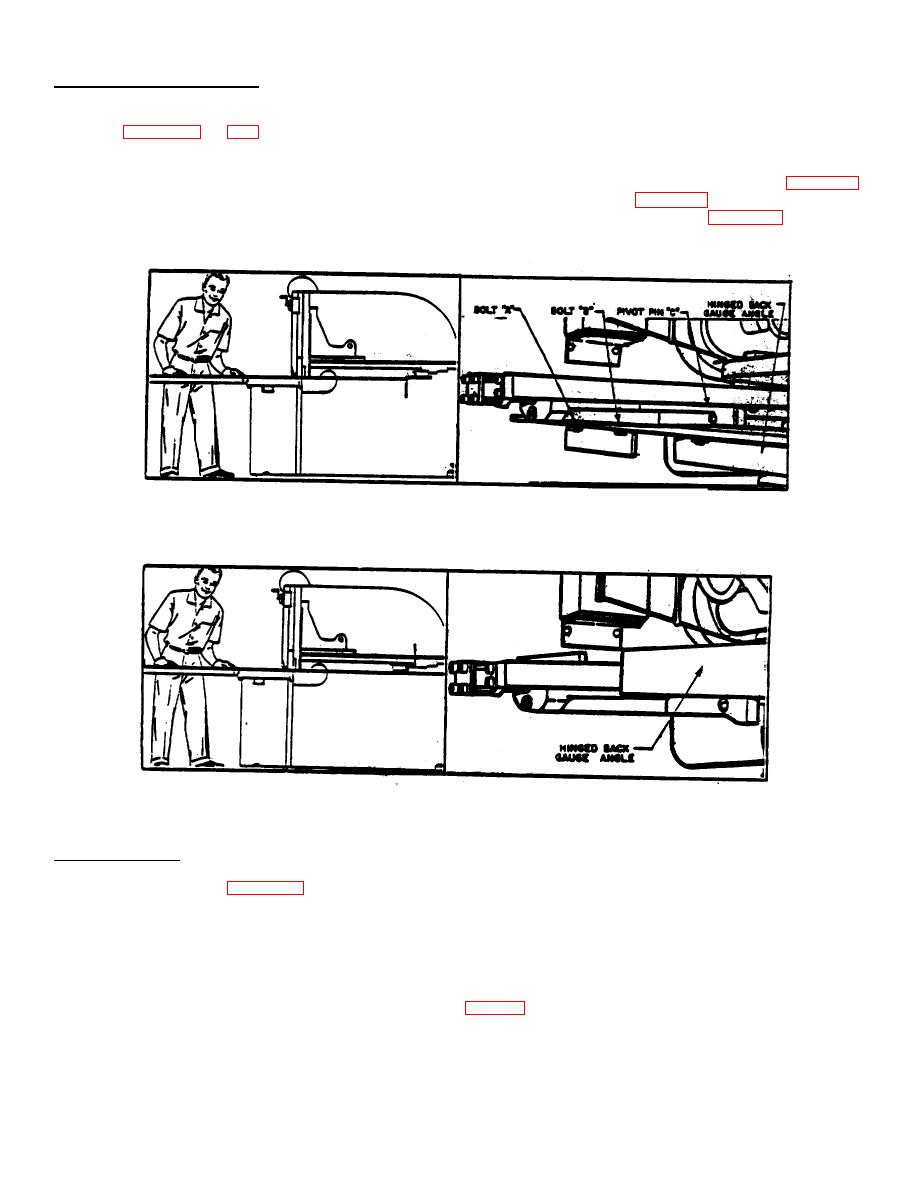
HINGE BACK GAUGE ANGLE
If material longer than the range of the back gauge is to be sheared, a Hinged Back Gauge Angle can be furnished at
extra cost (Figures 37 and 38).
To change the back gauge angle from its use as a stop, it is swung up and out of the way. To accomplish this,
remove the two bolts on each of the back gauge angle holding it to the back gauge carriage (Bolts "A" and "B", Figure 37).
When the bolts have been removed, the back gauge angle will hinge on pivot pin "C", Figure 37./ On the smaller, short
length machined, it is easy matter to now swing the back gauge angle up and over as shown in Figure 38. On larger,
longer machines, it is an advantage to use long handled adjustable end wrench to assist in turning the angle. Bolts "A"
and "B" are then used to hold the angle in the "Up" position and are inserted from the top.
Figure 37. Hinge Back Gauge Angle in the "Down" Position When Being Used as a Back Gauge Stop
Figure 38. Hinge Back Angle in the "UP" Position When the Shear is Being Used to Shear Material Longer than the Back
Gauge Range
SLITTING GAUGE
The Slitting Gauge (Figure 39) is an accessory that can be furnished at extra cost when ordered. Its primary
purpose is to help guide material across the shear table during slitting operations. The Slitting Gauge is bolted to the left
end of the shear table on shears that cut from left to right. Special order shears that cut from right to left would require a
Slitting Gauge that is bolted to the right end of the shear table.
To properly use the Slitting Gauge, the following steps should be followed:
(1)
Adjust ram for slitting (see previous instructions on page 31).
(2)
Set front gauge bar to correct distance by measuring from cutting edge of the lower blade.
(3)
Insert material into throat of machine from right side (from left side if the shear cuts from right to left) keeping it
against the front gauge bar-about half-way the length of the table.
34

