
TM 9-4120-370-14
TO 35E9-229-1
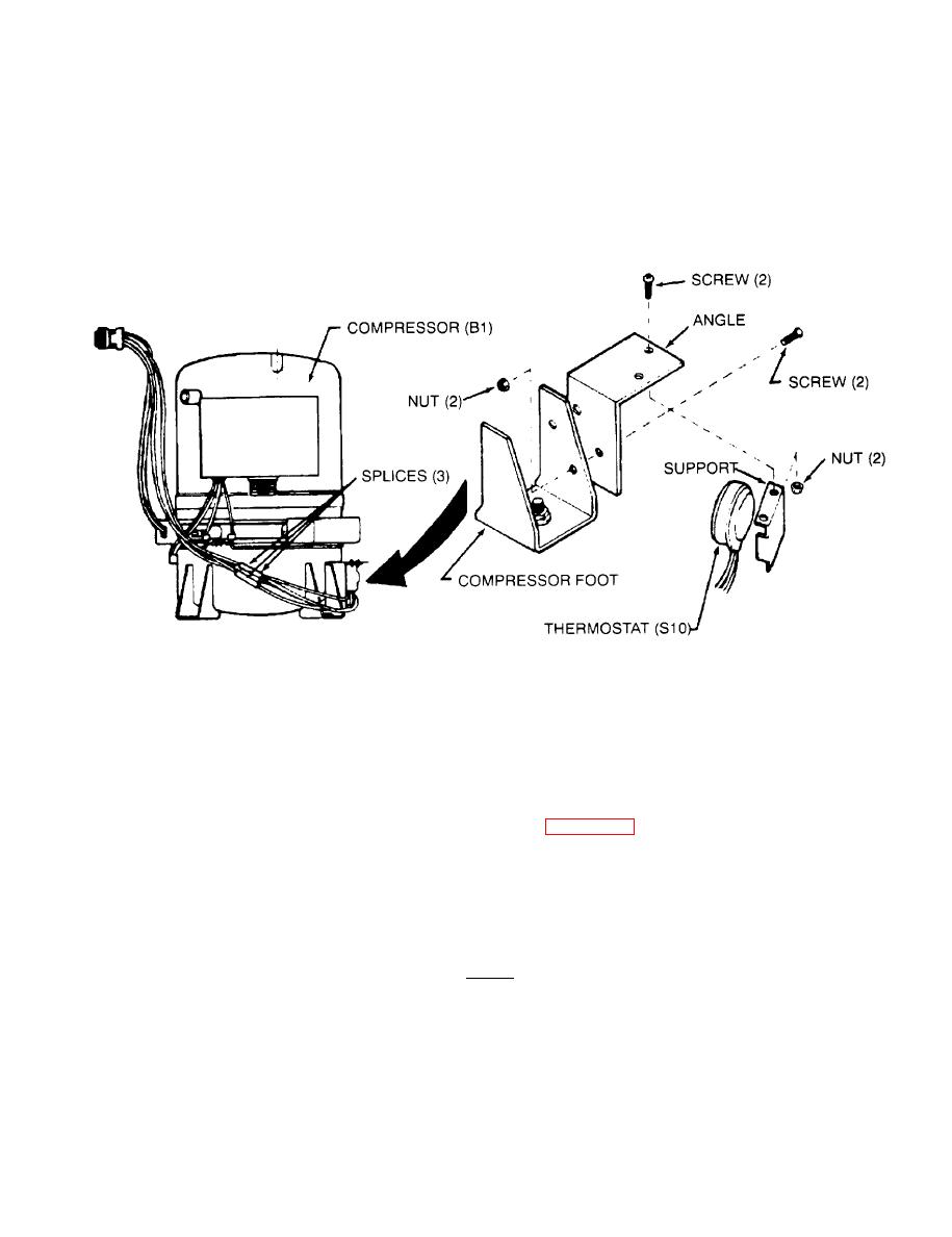
5-20. COMPRESSOR (B1) - Continued.
Thermostat (S10) replacement. (Refrigerant system discharge is not required.)
f.
(1)
Check to see that the power has been disconnected at the power source and covers have been removed
during access and testing.
(2)
Tag and disconnect leads at splices.
(3) Using screwdriver, remove two screws and nuts that secure support to angle.
(4) Remove support and thermostat (S10).
(5) Install new thermostat as follows:
(a) Using screwdriver, install support and thermostat with two screws and nuts. Be sure thermostat face
is making good contact with side of compressor.
(b) See tags on old thermostat and wiring diagram (Figure 4-20). Install new splices and connect leads.
Compressor replacement
g.
(1)
Check to see that the power has been disconnected at the power source, connectors (P21 and P11) were
disconnected and that covers have been removed during access and test.
(2)
Using screwdriver, remove two screws and flat washers. Disconnect the (P2) connector from the condens-
er fan motor and pull the connector mounting bracket out of the way.
NOTE
The compressor is mounted to the cabinet base by four bolts that are inserted from the
underside of the base. In order to remove the compressor, it is necessary that the entire
air conditioner be raised and placed on blocks of sufficient height to allow for removal
of these bolts from below the base.
Attach an overhead hoist to the lifting fitting on each side of the cabinet, using a sling and spreader bar.
(3)
(4)
Raise the cabinet and place it on blocks at least four inches high. Be sure the blocks do not obstruct the
holes in the base through which the compressor mounting bolts must be removed.

