
TM 9-4120-370-14
TO 35E9-229-1
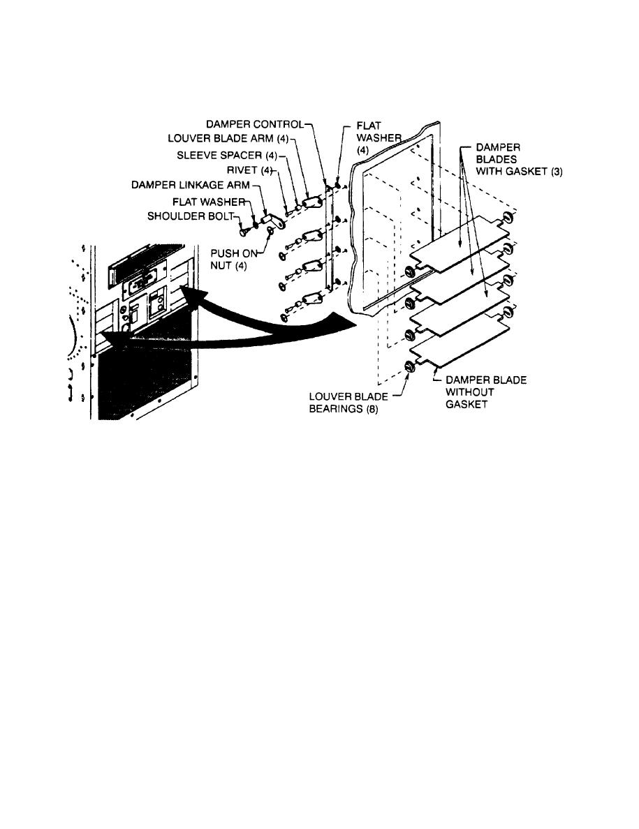
6-3. DAMPER PARTS (MODELS F36T4-2S, F36T4-2SA, AND F36T-2S ONLY) - Continued.
Inspection
a.
(1) Check for loose, missing, or broken parts. Repair loose parts and replace missing or broken parts.
(2) Check that damper blades are not bent, dented, or otherwise damaged. Straighten or replace damaged
blades.
(3) Check that gaskets are not loose or missing from upper three blades.
b . Removal
(1)
Remove push on nuts from ends of damper blades.
(2)
Using wrench, remove shoulder bolt and flat washers from damper linkage arm. This is the attachment
point for the actuating cylinder.
Carefully flex the damper blades enough to free the shorter tab end located toward the outer walls.
(3)
(4)
Remove damper blades and bearings.
If disassembly of the linkage parts is required, use a drill bit slightly smaller than the body diameter of the
(5)
rivet. Drill the rivets out and remove remaining parts.
Installation
c.
(1) f linkage parts were disassembled, bench assemble the linkage items that rivet together prior to installa-
tion. If linkage parts were not disassembled, go to step (6).
(2) Insert sleeve spacers through damper control and louver blade arms.

