
TM 9-4120-371-14
Section Ill TECHNICAL PRINCIPLES OF OPERATION
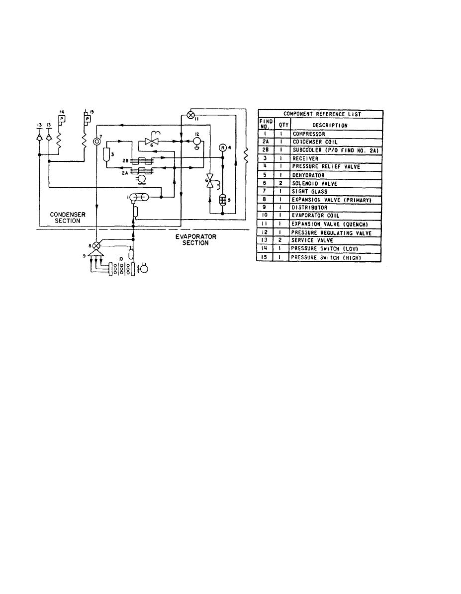
Figure 1-3. Refrigeration Schematic
a. Cooling cycle. Unit operation with mode selector switch set on COOL and the temperature control
thermostat set to DECREASE.
Compressor (1) starts.
To prevent compressor overload and damage during startup, equalizer solenoid valve (6) is open at
start of cooling cycle to equalize pressure on both sides of the compressor.
The compressor (1) takes cold, Iow pressure refrigerant gas and compresses it to a high temperature,
high pressure gas. This gas flows through the metal tubing to the condenser coil (2A and 2B) and receiver (3).
The condenser fan draws outside ambient air over and through the condenser coil (2A and 2B). The
high temperature, high pressure gas from the compressor (1) is cooled by the flow of air and is changed into a
high pressure liquid.
The dehydrator (filter drier) (5) removes any moisture (water vapor) or dirt that may be carried by the
liquid refrigerant.
The sight glass (liquid indicator) (7) indicates the presence of moisture and quantity of refrigerant in the
system.
The liquid line solenoid valve (6) is controlled by the temperature control thermostat on the control
panel. This valve will shut off the flow of refrigerant to the evaporator section when the temperature in the
conditioned area reaches the set point.

