
TM 9-4120-385-14
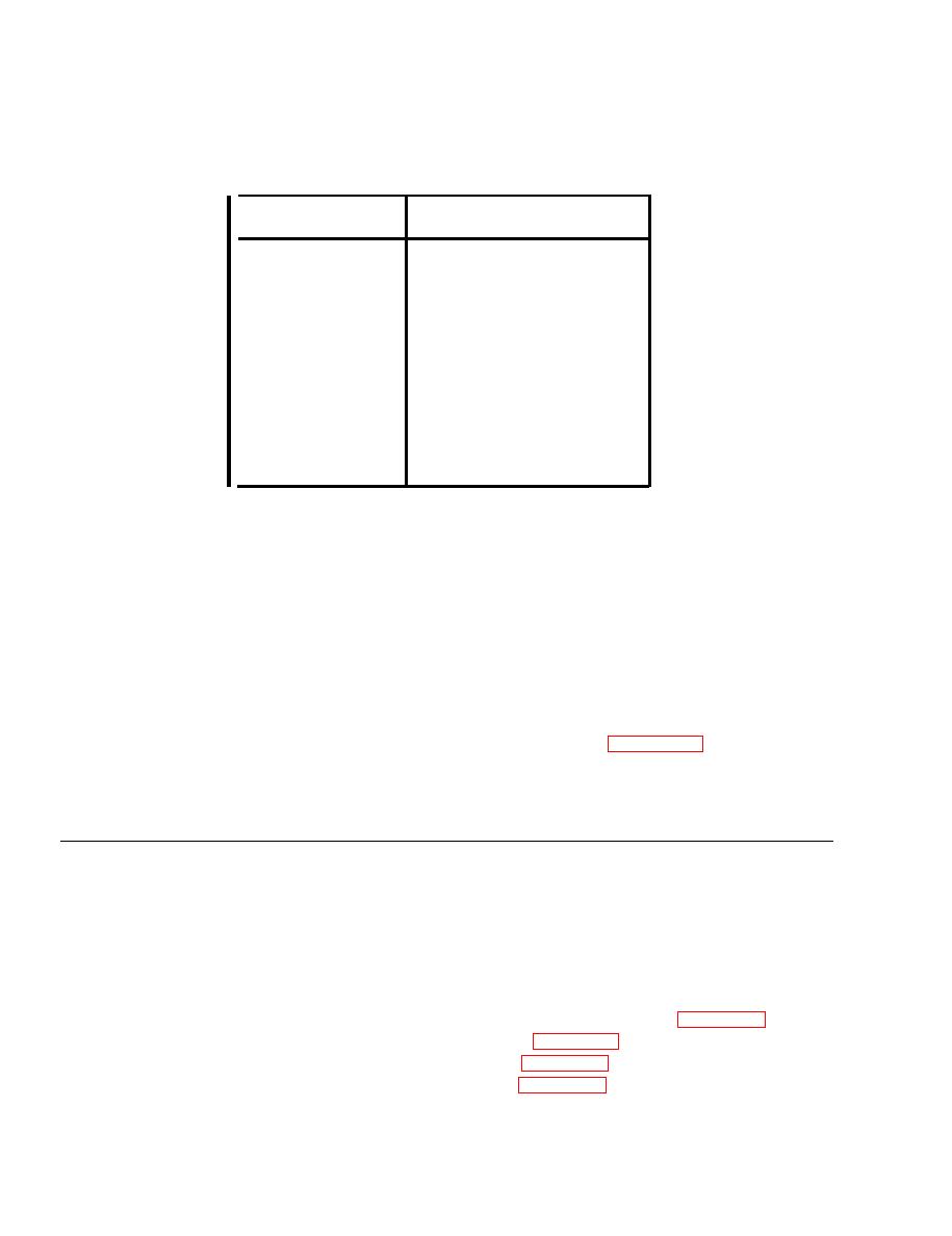
Table 4-15. HEATERS (HT1-HT6) TERMINAL CONNECTIONS
WIRE NO.
HEATER.
J7-A
HR1
S3-6
HR1
HR2
J7-A
S3-6
HR2
J7-A
HR3
S3-6
HR3
HR4
J7-B
HR4
S3-5
J7-B
HR5
S3-5
HR5
J7-B
HR6
S3-5
HR6
2.
Check for continuity between each heater terminal and element. If continuity is
indicated, element is defective and should be replaced.
INSTALLATION.
d.
1.
Secure each floating nut (6) to support (4) with two rivets (5), if necessary.
Attach support (4) to casing using four screws (l), flat washers, (3) and nuts (2),
2.
if necessary.
Mount heating elements (11) with clamps (10) and tighten panel fasteners (8).
3.
4.
Connect electrical leads to heating elements. Refer to Table 4-15 for correct
connections.
4-27. EVAPORATOR and CONDENSER COILS
This task covers:
a . Inspection
b . Cleaning
INITIAL SETUP
Equipment Condition
Condition Description
Para
Canvas cover, top and lower panels removed (Para 4-10)
4-10
Condenser guard removed (Para 4-11)
4-11
Discharge grille removed (Para 4-12)
4-12
Mist eliminator removed (Para 4-15)
4-15
4-94

