
TM 9-4120-388-14
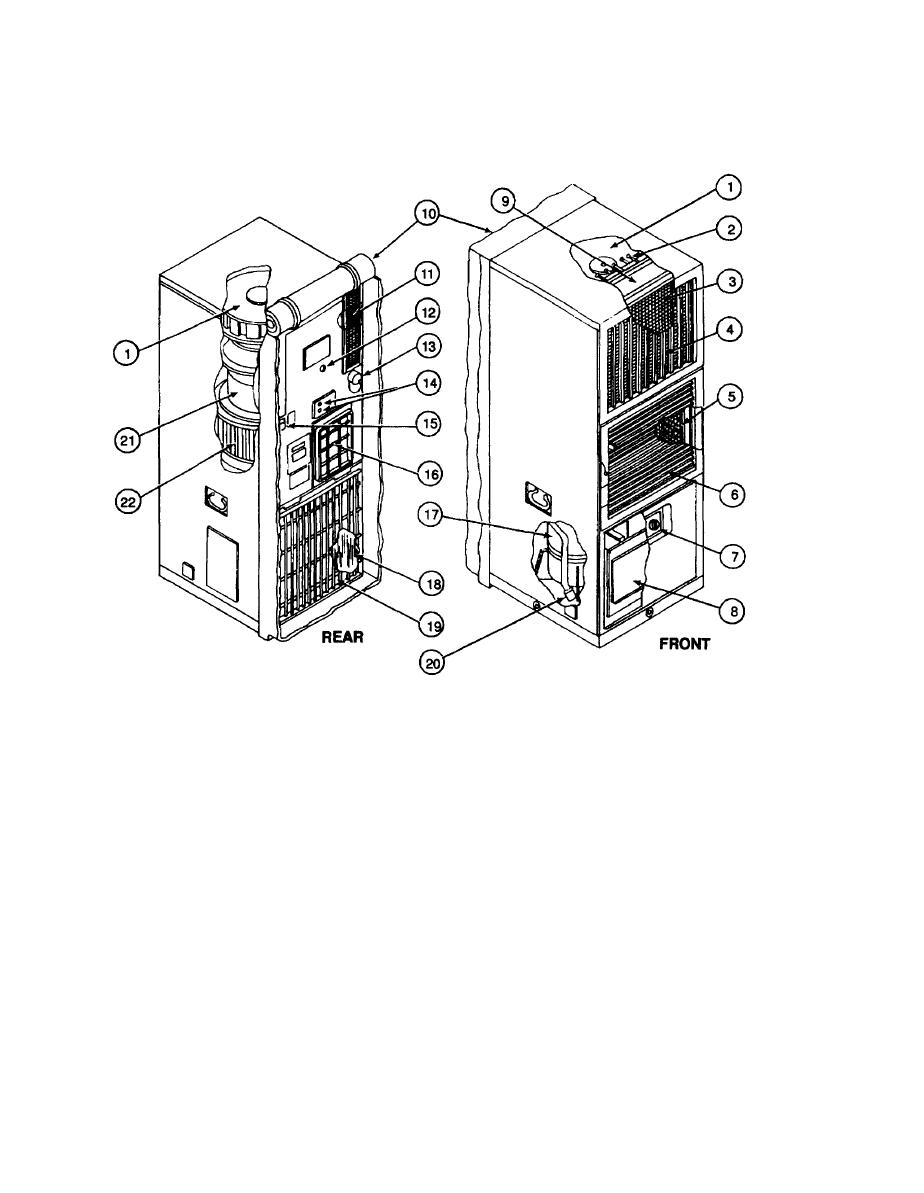
1-7. LOCATION AND DESCRIPTION OF MAJOR COMPONENTS.
1.
CONDITIONED AIR (EVAPORATOR) FAN - Draws air into the evaporator section and exhausts it through the evaporator
(cooling) coil and heater elements into the room or enclosure.
2.
HEATER ELEMENTS (HR 1 through HR 6) - Consists of two banks of three elements each. Only one bank operates in
the LO HEAT mode. Both banks operate in the HI HEAT mode, however the temperature control thermostat controls only
one bank.
MIST ELIMINATOR - Prevents condensate (water) from being blown from the coil into the room or enclosure.
3.
CONDITIONED AIR DISCHARGE GRILLE - Adjustable louvers allow directional control of conditioned air.
4.
RETURN AIR FILTER - Provides filtered return air.
5.
INTAKE (RETURN) AIR GRILLE - Adjustable louvers allow control of outside (fresh) and return (from room or enclosure)
6.
air.
7.
CONTROL PANEL - Contains a five position mode selector switch and a temperature control thermostat.
JUNCTION BOX - Contains and protects electrical system control devices.
8.
EVAPORATOR COIL - Serves as a heat exchanger by transferring heat from the air passing over the tubing and
9.
fins to the refrigerant passing through the tubing.
FABRIC COVER - Shown on rearview in stowed (operational) position. When rolled down and snapped it protects
10.
the rear (exposed) surface of the unit.
FRESH AIR FILTER AND DAMPER - Provides filtered outside air.
11.

