
TM 9-4120-388-14
This task covers:
a. Inspection/Test
b. Removal
c. Installation
INITIAL SETUP:
Equipment Condition
Rear panel removed (4-31).
Inspection/Test.
a.
(1) Check to see that power has been disconnected.
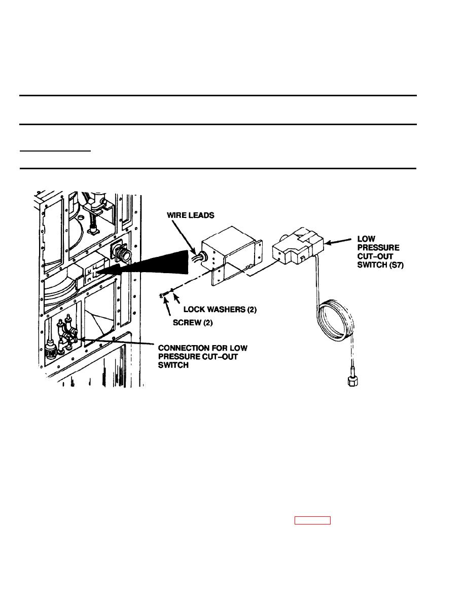
(2) Remove two screws and Iockwashers from switch.
(3) Carefully pull switch from box far enough to gain access to terminals. Remove protective clip-on cap.
(4) Be sure that wire leads and terminal attachment screws are in place and secure. Tighten if loose. Replace
if missing.
(5) Be sure that capillary line is not kinked, mashed, or broken. Replace switch if capillary line is damaged.
NOTE
Be sure that refrigerant system is properly charged. (See para 5-12.)
(6) Press and release the reset button to be sure switch is not tripped.
(7) Use a continuity tester or multimeter to check for continuity between terminals 1 and 2 on switch. If there
is continuity, the switch is properly closed. If no continuity is found, switch must be replaced.

