
TM9-4120-400-14
COMPRESSOR.
c. Repair
d. Installation
b. Removal
a. Testing
This task covers:
INITIAL SETUP
Equipment Condition
Tools
Remove top rear panel (para 4-11).
Refrigeration Unit Service Tool Kit
Appendix B, item 1
General Safety Instructions_
Materials/Parts
Compressor
Thermal Overload Switch
Crankcase Heater
If compressor is being removed due to burnout, use care
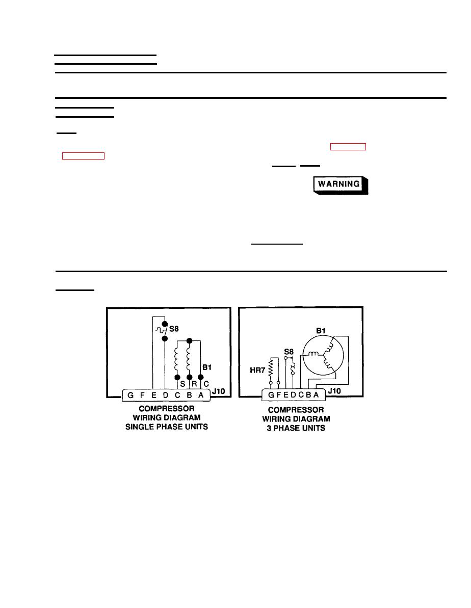
Connector J10
when lifting to avoid touching compressor sludge. Acid
Self-locking Nut
in sludge can cause burns.
Tie Down Straps
Personnel Required
Two
TESTING
Figure 5-31
Compressor Testing
1.
Disconnect wiring harness P10 from J10.
2.
(On 3 phase models only.) With multimeter set on lowest OHMS scale, check for continuity between pins G
and F in connector J10. If there is no continuity between these pins, heater is bad and should be replaced.
3.
Check continuity between pins D and E. If there is no continuity between these pins, and the compressor has
had time to cool down, the compressor motor internal overload switch (S8) is bad. On three phase units,
replace compressor. On single phase units, replace overload protector.
5-75

